Posts

Showing posts with the label Alarm

Bicycle Alarm Schematics Diagram

Image
The author wanted a very cheap and simple alarm for some of his possessions, such as his electrically assisted bicycle. This alarm is based on a cheap window alarm, which has a time-switch added to it with a 1-minute time-out. The output  pulse of the 555 replaces the reed switch in the window alarm. The 555 is triggered by a sensor mounted near the front  wheel, in combination with a magnet that is mounted on the spokes. This sensor and the magnet were taken from a cheap bicycle computer. The front wheel of the bicycle is kept unlocked, so that the reed  switch closes momentarily when the wheel turns. This  triggers the 555, which in turn activates the window alarm. The circuit around the 555 takes very little current and can  be powered by the batteries in the window alarm.  There  is just enough room  left inside the enclosure of the window  alarm to mount the time-switch inside it. Bicycle Alarm Schematics Diagram The result is a very che...

Simple Purpose Alarm

Image
The alarm may be used for a variety of applications, such as frost monitor, room temperature monitor, and so on. In the quiescent state, the circuit draws a current of only a few microamperes, so that, in theory at least, a 9 V dry battery (PP3, 6AM6, MN1604, 6LR61) should last for up to ten years. Such a tiny current is not possible when ICs are used, and the circuit is therefore a discrete design. Every four seconds a measuring bridge, which actuates a Schmitt trigger, is switched on for 150 ms by a clock generator. In that period of 150 ms, the resistance of an NTC thermistor, R11, is compared with that of a fixed resistor. If the former is less than the latter, the alarm is set off. When the circuit is switched on, capacitor C1 is not charged and transistors T1–T3 are off. After switch-on, C1 is charged gradually via R1, R7, and R8, until the base voltage of T1 exceeds the threshold bias. Transistor T1 then comes on and causes T2 and T3 to conduct also. Thereupon, C1 is charged via...

Power Supply Failure Alarm

Image
Most of the power supply failure indicator circuits need a separate power-supply for them-selves. But the alarm circuit presented here needs no additional supply source. It employs an electrolytic capacitor to store adequate charge, to feed power to the alarm circuit which sounds an alarm for a reasonable duration when the mains supply fails. During the presence of mains power supply, the rectified mains voltage is stepped down to a required low level. Power Supply Failure Alarm Circuit Diagram: A zener is used to limit the filtered voltage to 15-volt level. Mains presence is indicated by an LED. The low-level DC is used for charging capacitor C3 and reverse biasing switching transistor T1. Thus, transistor T1 remains cut-off as long as the mains supply is present. As soon as the mains power fails, the charge stored in the capacitor acts as a power-supply source for transistor T1. Since, in the absence of mains supply, the base of transistor is pulled ‘low’ via resistor R8, it conduct...

Light Alarm Circuit Diagram

Image
LIGHT ALARM - 1 This circuit operates when lightweight|the sunshine} Dependent Resistor receives light. When no lightweight falls on the LDR, its resistance is high and also the transistor driving the speaker isn't turned on. When lightweight falls on the LDR its resistance decreases and also the collector of the second transistor falls. This turns off the primary transistor slightly via the second 100n and also the initial 100n puts a further spike into the bottom of the second transistor. This continues till the second transistor is turned on as onerous because it will go. the primary 100n is currently nearly charged and it cannot keep the second transistor turned on. The second transistor starts to turn off and each transistors swap conditions to provide the second half of the cycle. LIGHT ALARM - 2 This circuit is comparable to lightweight Alarm -1 however produces a louder output as a result of the speaker being connected directly to the circuit. The circuit is essentially a h...

Auto Alarm Schematic

Image
In operation, the alarm circuit allows a 0 - 47 second time delay, as determined by the R1 /C1 combination, after the switch is armed to allow the vehicle's motion sensor to settle down. This allows you time to get a bag of groceries out of the trunk and not have the hassle of juggling the groceries and the key switch at once. During the time delay, half of LED1, which is actually a single, bi-colored, three-legged common cathode device, lights green. At the same time, pins 8 and 4 of U2 (a 555 oscillator/timer) are held low by Ul (a 3905 oscillator/timer), causing the alarm to remain silent. Once the delay is over, LED1 turns red, indicating that the circuit is armed. Auto Alarm Schematic Circuit Diagram At that point, a ground at pin 2 of U2 forces pin 3 of U2 high, closing the contacts of Kl and sounding the siren for a time duration determined by R4 and C2. Once the time has elapsed, pin 3 is pulled low, Kl opens, and the circuit is again ready to go. The circuit can be manuall...

Wire Break Alarm With Delay Circuits Diagram

Image
Simple Wire-Break Alarm With Delay  Alarm and Security Here is a simple circuit of wire-break alarm that activates after a delay of 15 to 30 seconds. When the thin-wire loop running across the entrance door is broken, the alarm sounds after a delay of 15 to 30 seconds, the time period set through VR1. Thus the occupants get sufficient time to lock the room from the outside and catch the thief.   The circuit uses CD4060, which is a 14-stage ripple-carry binary counter/divider and oscillator. It is wired as a timer here and does not need input pulse for trigger. CD4060 gets activated as soon as the power supply is switched on. Output O13 of CD4060 goes high after the lapse of preset delay set through VR1. Transistor SL100 (T2) is wired as a switch to power the timer section built around CD4060. When the wire loop is closed, transistor T2 does not conduct. So power to the timer circuit is not available and the piezo buzzer does not sound.  Wire-Break Alarm With Delay ...

Pyro Electric Fire Alarm

Image
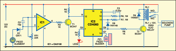
Here is an ultra-sensitive fire sensor that exploits the direct piezoelectric property of an ordinary piezo element to detect fire. The lead zircon ate titan ate crystals in the piezo element have the property to deform and generate an electric gate protected p-channel MOSFETs in the inputs. It has high speed of performance and low input current requirements.There are two inputs—the non-inverting input (pin 3) connected to the piezo element through diode D7 (OA71) that carries the voltage signal from the piezo element and the inverting input (pin 2) that gets a preset voltage momentarily changes the voltage level at pin 3 of IC1 and its output swings high. Transistor T1 conducts taking the reset pin 12 of IC2 to ground. IC2 is now enabled and starts oscillating. With the shown values of the oscillating components C3 (0.22μ) and R6 potential when heated, thus converting the piezo element into a heat sensor. The circuit described here is very sensitive. It gives a warning alarm if ...

Burglar Alarm System Circuit

Image
This burglar alarm system circuit is using a infrared proximity detector that triggers an alarm when the rays falling on its sensor are interrupted. It is different from others burglar alarm systems because is a very simple diy project and can offer you great satisfaction. The circuit of IR burglar alarm system comprises transmitter and receiver-cum-alarm sections. It works off 6V DC, 500mA uninterrupted supply and uses low-cost readily-available electronic components. LED2 is used for indicating power-on. Check out the infrared alarm circuit too. Burglar alarm circuit diagram The transmitted IR signal directly falls on IR sensor TSOP1738. Whenever the IR signal is interrupted, its output pin 3 goes low and IC2 is triggered at pin 5 through transistor T2. As a result, its output at pin 7 goes low (for a preset time) to forward bias siren-driver transistor T2. This condition is indicated by the glowing of LED1. The time-out period can be increased or decreased by changing the value of ...

Build a Radio Wave Alarm

Image
This simple circuit is sure to have the police beating a path to your door- however, it has the added advantage of alerting you to their presence even before their footsteps fall on the doormat. Simple Radio Wave Alarm Circuit Diagram : Notes : The circuit transmits on Medium Wave (this is the small problem with the police). IC1a, together with a sensor (try a 20cm x 20cm sheet of tin foil) oscillates at just over 1MHz. This is modulated by an audio frequency (a continuous beep) produced by IC1b. When a hand or a foot approaches the sensor, the frequency of the transmitter (IC1a) drops appreciably. Suppose now that the circuit transmits at 1MHz. Suppose also that your radio is tuned to a frequency just below this. The 1MHz transmission will therefore not be heard by the radio. But bring a hand or a foot near to the sensor, and the transmitter's frequency will drop, and a beep will be heard from the radio. Attach the antenna to a multiplug adapter that is plugged into the mains, a...

Usng Lm 358 Siren Alarm Circuit Diagram

Image
This is the simple ic based Siren Alarm Circuit Diagram.  This siren alarm circuit may provide the final building block in an alarm circuit using a relay to activate it. This siren circuit is very simple and is constructed using common electronic components .  Siren Alarm Circuit Diagram When the switch is pressed C3 charges up through R4 with a time constant of 0.47 seconds and when the switch is released C3 begins a slower discharge through R7 and R3 with a time constant of about 5 seconds. The op amp 358 used in this project is set up as a voltage controlled oscillator. When the output of the oscillator (pin 7) switches low there is a charge remaining in C1 which holds pin 5 below the switching point. Current through R7 is proportional to the control voltage on C3. This current discharges C1 causing the voltage on pin 5 to rise towards the switching point at a rate proportional to the voltage on C3. When the switching point is reached pin 7 switches high and initially pulls...

Power Supply Failure Alarm

Image
Most of the circuit power supply failure alarm circuits require additional or external power supply. However, this circuit requires no additional power supply. The circuit uses a voltage of 5 volts to 15 volts. To adjust the voltage of this circuit, first connect the power source (5 to 15V) and change the position of potentiometer VR1 until the buzzer buzzer On to Off position. If the power supply fails, resistor R2 will bias the transistor and the base will turn on the buzzer. Here is a picture series of power supply failure alarm :  Power Supply Failure Alarm  Circuit

Refrigerator Door Alarm

Image
Do your kids leave the door to the refrigerator open? Or does your celery reach out to keep the door from closing properly when you turn your back? Here's a simple circuit that beeps whenever the door is open for an extended period of time (which will also put a little pressure on the fridge loiterers in the house). Simple Refrigerator Door Alarm Circuit Diagram  The photocell has a very high resistance in the dark which drops very low when the door opens and the light turns on. The 22 uF capacitor begins to charge and when the voltage reaches the zener voltage, the beeper sounds. Closing the door allows the capacitor to discharge through the 10 meg.  resistor, resetting the beeper. The circuit draws very little power when the door is shut and only draws significant current when the beeper is sounding. The transistor may be a single NPN darlington such as the MPS-A14 or two 2N4401's connected as shown. Other types will also work. The delay may be changed by changing the value ...

Make a Photodiode Alarm

Image
This Photodiode based Alarm can be used to give a warning alarm when someone passes through a protected area. The circuit is kept standby through a laser beam or IR beam focused on to the Photodiode. When the beam path breaks, alarm will be triggered. The circuit uses a PN Photodiode in the reverse bias mode to detect light intensity. In the presence of Laser / IR rays, the Photodiode conducts and provides base bias to T1. The NPN transistor T1 conducts and takes the reset pin 4 of IC1 to ground potential. IC1 is wired as an Astable oscillator using the components R3, VR1 and C3. The Astable operates only when its resent pin becomes high. When the Laser / IR beam breaks, current thorough the Photodiode ceases and T1 turns off. The collector voltage of T1 then goes high and enables IC1. The output pulses from IC1 drives the speaker and alarm tone will be generated. Photo-Diode Alarm Circuit IR Transmitter Circuit A simple IR transmitter circuit is given which uses Continuous IR rays. Th...

Water Alarm Circuit Diagram

Image
The LM1830 fluid detector IC from National Semiconduc tor is designed to be able to detect the presence of fluids using a probe. This chip requires a relatively high supply voltage and is not the most frugal power consumer. It is also quite specialised so unless you are buying in bulk the one-off price is not cheap.  An alternative circuit show n her e uses a standard CMOS IC type 74HC14. It has the advantage of operating with a 3 V supply and consumes less than 1 µA when the alarm is not sounding, this makes it ideal for use with batteries.  Water Alarm Schematic Circuit Diagram The 74HC14 has six inverters with hysteresis on their input switching thresholds. A capacitor (C1) and a feedback resistor (R1) is all that’s necessary to make an inverter into a square wave signal generator.  In the water alarm circuit the feedback resistor consists of R1 and the water sensor in series. R1 prevents any possibility of short-circuit between the inverter’s input and out-put. Resis...

Magnetic Reed Switch Alarm

Image
This circuit is made to be an alarm, both for home and handbags. If it is installed for home it will placed on door or windows, and if it is installed for bags or handbags it will placed in the bag. This circuit consists of a small magnet and a reed switch. If the magnet looses its contact with the reed switch, SW1 opens, the circuit starts oscillating and the loudspeaker emits a loud alarm sound.so this circuit suitable for use as an anti-theft alarm. This circuit uses A complementary transistor-pair which is wired as a high efficiency oscillator, directly driving a small loudspeaker. Low part-count and 3V battery supply enable a very compact construction. Notes : The loudspeaker’s dimensions are limited only by the box that contain it. An on-off switch is unnecessary because the stand-by current drawing is less than 20µA. Current consumption when the alarm is sounding is about 100mA. If the circuit is used as anti-bag-snatching, SW1 can be replaced by a 3.5mm mono Jack socket and the...

Single Zone Alarm Circuit Diagram

Image
Description:   A single zone alarm circuit with entry and exit delay and other facilities. Circuit Diagram Notes: The circuit features automatic exit and entry delays, timed bell cut-off and system reset. It has provision for normally open and normally closed switches and will suit the usual input devices (Pressure Mats, Magnetic Reed contacts, Foil Tape, PIRs and Inertia Sensors). When the power is applied, if there's a fault the buzzer will sound and you should switch off again and check for open doors, windows, etc. If everything is in order the buzzer will NOT sound and the exit delay will begin. You have about 30 seconds to leave the building. When you return the buzzer will sound. You then have about 30 seconds to switch off; otherwise the siren will sound. It will go on sounding indefinitely. However, if the building is re-secured the siren will switch off after about 10 minutes and the alarm will reset. The Exit delay, Entry delay and Bell Cut-off times can be changed by al...

Power Supply Failure Alarm

Image
Most of the circuit power supply failure alarm circuits require additional or external power supply. However, this circuit requires no additional power supply. The circuit uses a voltage of 5 volts to 15 volts. To adjust the voltage of this circuit, first connect the power source (5 to 15V) and change the position of potentiometer VR1 until the buzzer buzzer On to Off position. If the power supply fails, resistor R2 will bias the transistor and the base will turn on the buzzer. Here is a picture series of power supply failure alarm :  Power Supply Failure Alarm  Circuit

Motorbike Alarm

Image
This simple to build alarm can be fitted in bikes to protect them from being stolen. The tiny circuit can be hidden anywhere, without any complicated wiring. Virtually, it suits all bikes as long as they have a battery. It doesn't drain out the battery though as the standby current is zero. The hidden switch S1 can be a small push-to-on switch, or a reed switch with magnet, or any other similar simple arrangement. The circuit is designed around a couple of low-voltage MOSFETs configured as monostable timers. Motorbike key S2 is an ignition switch, while switch S3 is a tilt switch. Motorbike key S2 provides power supply to the gate of MOSFET T2, when turned on. When you turn ignition off using key S2, you have approximately 15 seconds to get off the bike; this function is performed by resistor R6 to discharge capacitor C3. Thereafter, if anyone attempts to get on the bike or move it, the alarm sounds for approximately15 seconds and also disconnects the ignition circuit. During park...

Refrigerator Door Alarm Circuit Diagram

Image
Do your kids leave the door to the refrigerator open? Or does your celery reach out to keep the door from closing properly when you turn your back? Here's a simple circuit that beeps whenever the door is open for an extended period of time (which will also put a little pressure on the fridge loiterers in the house).  Simple Refrigerator Door Alarm Circuit Diagram  The photocell has a very high resistance in the dark which drops very low when the door opens and the light turns on. The 22 uF capacitor begins to charge and when the voltage reaches the zener voltage, the beeper sounds. Closing the door allows the capacitor to discharge through the 10 meg.  resistor, resetting the beeper. The circuit draws very little power when the door is shut and only draws significant current when the beeper is sounding. The transistor may be a single NPN darlington such as the MPS-A14 or two 2N4401's connected as shown. Other types will also work. The delay may be changed by changing the ...

Burglar Alarm Using LDR and BC 548 Circuit diagram

Image
Description  Circuit showing a Burglar Alarm.Here we have used a ldr and a switching transistor for making this circuit .When the light coming towards the ldr during the period the ldr have low resistance so the buzzer will on.When the light going away the ldr during the period the ldr have high resistance so the transistor will off.Here you need a 12 volt power supply Burglar Alarm Using LDR and BC 548 Circuit diagram    Components Required       Resistor                    10 k(preset)       Transistor                    BC 548        LDR         Buzzer