Posts

Showing posts with the label Doorbell

A Doorbell for the Deaf

Image
This circuit provides a delayed visual indication when a door bell switch is pressed. In addition, a DPDT switch can be moved from within the house which will light a lamp in the door bell switch. The lamp can illuminate the words "Please Wait" for anyone with walking difficulties.  A Doorbell for the Deaf Circuit Diagram : Notes : The circuit uses standard 2 wire doorbell cable or loudspeaker wire. In parallel with the doorbell switch, S1, is a 1N4001 diode and a 12 volt 60mA bulb. The bulb is optional, it may be useful for anyone who is slow to answer the door, all you need to do is flick a switch inside the house, and the bulb will illuminate a label saying Please Wait inside the doorbell switch or close to it. The double pole double throw switch sends the doorbell supply to the lamp, the 22 ohm resistor is there to reduce current flow, should the doorbell switch, S1 be pressed while the lamp is on. The resistor needs to be rated 10 watts, the 0.5 Amp fuse protects agains...

Doorbell Memory Circuit Diagram

Image
Description  If you’re expecting an important visitor but you just have to step out for a moment, an electronic doorbell memory can come in handy so you can see whether someone rang while you were out. Of course, you can’t tell whether it was the visitor you were expecting who dropped by then, but a call to the mobile phone of the person concerned can quickly answer that question. A doorbell memory can also save you the trouble of going to the front door (if you live upstairs) when you think you heard the bell but aren’t sure. And if you can’t buy one, then of course you can build one yourself! Read on to find out how.  Circuit Diagram: Circuit Description:  It takes only a handful of electronic components to build a handy tale-tale with an LED that indicates whether someone pressed the button of your doorbell. How many times have you thought you heard your doorbell while watching television in the evening? The sound of the well-known ‘ding–dong’ chimes occurs all too oft...

Doorbell with IC555

Image
All components arranged as in the picture sequence below. Current will flow starting from the source voltage and to the switch. When the switch is closed current will flow through the diode, where diode serves as a switch is closed because it was given forward bias (anode diode is given positive voltage and the cathode is given a negative voltage). 2 Tones Doorbel Schematic with IC555 Flows will be divided into two to D1 and D2. Flows from D1 (diode 1) will be channeled towards R3 and proceed toward IC555 pin7 and pin 6. Pin 7 (Discharge) serves as an audible tone interval timing, and pin 6 (threshold) to determine the final timing tone, flow at D2 will be divided into three, heading polar capacitors, resistors, and IC555 pin 4. Polar capacitors are capacitors that have poles. The current through the capacitor and R1 polar probe + will go to the speakers. IC555 pin 4 is reset, as the timing interval can be interrupted by giving the reset pulse 0V....

Doorbell with Counter Circuit Diagram

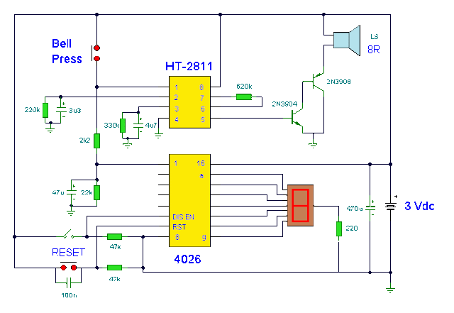
Image
This circuit is a doorbell with counter , that means it counts how many times the bell is triggered . It uses a chip synthesizer sound, the HT -2811 ms nothing prevents you from using another device sound generator . The HT -2811 reproduces the sound of a " ding-dong" doorbell . Besides this ic , the circuit includes a CMOS 4026 and Display Driver IC which counts the total number of visitors .  Electronic Doorbell with Counter Circuit Diagram

Doorbell Memory

Image
If you’re expecting an important visitor but you just have to step out for a moment, an electronic doorbell memory can come in handy so you can see whether someone rang while you were out. Of course, you can’t tell whether it was the visitor you were expecting who dropped by then, but a call to the mobile phone of the person concerned can quickly answer that question. A doorbell memory can also save you the trouble of going to the front door (if you live upstairs) when you think you heard the bell but aren’t sure. And if you can’t buy one, then of course you can build one yourself! Read on to find out how. Circuit diagram: Doorbell Memory Circuit Schematic Circuit description: It takes only a handful of electronic components to build a handy tale-tale with an LED that indicates whether someone pressed the button of your doorbell. How many times have you thought you heard your doorbell while watching television in the evening? The sound of the well-known ‘ding–dong’ chimes occurs a...