Posts

Showing posts with the label Control

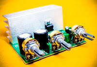
TDA2030 complete tone control
Image
At this time I present a series of amplifiers that use IC TDA2030, but this series is equipped with a tone control. Tone controls include Bass, Treebel, and Volume. Power amplifier and tone control has been put together in a single PCB. As well as its power supply circuit was also used as one with the power amp, and tone control. Making it easier in the installation and will look neat. Schematics Layout PCB PCB design This amplifier is a mono amplifier type, can be modif for guitar amplifiers. If not coupled amplifier (mic preamp) then you must deactivated potensio treble and bass, why? because if not using a mic preamp and still maintain potensio treble and bass sound input (input) from the guitar will not or the maximum discharge is not tight on the speakers. So you must deactivated a way to decide which directly connected capacitor with the tone control circuit, and capacitor were connected directly to potensio volume and input jack.

Hacking Car Wipers for Easy Control

Image
How do you want to have your wipers become more intelligent? In this way, they could remember how frequent you need to use them. But of course, this will need the help of an ATmega8L microcontroller. When you need to activate the wiper, you just press the button and it will run in one course. There is a 45 seconds waiting time that if you do not press the button, it will go on standby while telling itself that only one course is needed. The system will activate the wiper again if the button is pressed before 45 seconds. The good thing is that it will remember the interval when you pressed the button. Click here to visit the project page.

Simple Accurate Bass Tone Control

Image
A difficult problem in the design of conventional stereo tone controls is obtaining synchronous travel of the potentiometers. Even a slight error in synchrony can cause phase and amplitude differences between the two channels. Moreover, linear potentiometers are often used in such controls, and these give rise to unequal performance by human hearing. Special potentiometers that counter these difficulties are normally hard to obtain in retail shops. A good alternative is a control based on a rotary switch and a discrete potential divider. The problem with this that for good tone control more than six steps are needed, and switches for this are also not readily available. Fortunately, electronic circuits can remove these difficulties.     The analogue selectors used may be driven by mechanical switches, standard logic circuit or a microcontroller. The selectors used in the present circuit are Type SSM2404 versions from Analogue Devices, which switch noiselessly. Each IC contains...

Precision Amplifier With Digital Control

Image
This Precision Amplifier With Digital Control circuit diagram is similar to the preceding circuit of the attenuator. Gain of up to 100 can be achieved in this configuration, which is useful for signal conditioning of low output of transducers in millivolt range. The gain selection resistors R3 to R6 can be selected by the user and can be anywhere from 1 kilo-ohm to 1 meg-ohm. Trimpots can be used for obtaining any value of gain required by the user. The resistor values shown in the circuit are for decade gains suitable for an autoranging DPM. Resistor R1 and capacitor C1 reduce ripple in the input and also snub transients. Zeners Z1 and Z2 limit the input to ±4.7V, while the input current is limited by resistor R1. Capacitors C2 and C3 are the power supply decoupling capacitors. . Circuit diagram : Precision Amplifier With Digital Control Circuit Diagram Op-amp IC1 is used to increase the input impedance so that very low inputs are not loaded on measurement. The user can terminate the...

24VDC VARIABLE PWM SPEED CONTROL WITH AUTOSTOP

Image
VARIABLE PWM SPEED CONTROL

Telephone Record Control Circuit Diagram

Image
This circuit will allow you to connect any tape recorder that has a mic and remote input to a phone line and automatically record both sides of a conversation when ever the phone is in use. You will need to take a couple of voltage readings before connecting the circuit. First determine the polarity of your phone line and connect it to the circuit as shown and then determine the polarity of the remote input and connect it to the circuit. Circuit operation is as follows. When the phone is on hook the voltage across the phone line is about 48volts dc. When the phone is off hook the voltage will drop to below 10volts dc. When the line voltage is at 48volts the FET is off which causes Q2 and Q3 to be off. When the phone is picked up the FET turns on along with Q2 and Q3 which turns your recorder on. The tape recorder must be in the record mode at all times. As you can see the power source for the circuit is the phone line. Circuit Diagram

AC Power Control Adjustable Phase Angle Control with triac using ATmega8

Image
Principle of Phase Angle Control Top - Output Voltage Bottom - Gate Drive Signal Image source: Wikipedia (http://en.wikipedia.org/wiki/File:Regulated_rectifier.gif) The photo above clearly illustrates phase angle control: output voltage controlled by the gate drive signal applied to a thyristor. What is phase angle control? That is what I'm going to talk about in this article. Phase angle control is a method of PWM applied to AC input voltages, usually the mains supply. Of course, the AC supply could be from a transformer or any other AC source, but the mains supply is the most common input – this gives the phase angle control method its greatest usefulness. It has of course become quite obvious from the title (and I’m sure most of you reading will already know this) that the purpose of phase angle control is to control or limit power to the load. The power device used in phase angle controllers is a thyristor – mostly triacs or SCRs. (There are methods of phase controlling employi...

PWM Based Speed Control for DC Motors

Image
There are several methods for controlling the speed of DC motors. One simple method is to add series resistance using a rheostat. As considerable power is consumed in the rheostat, this method is not economical. Another method is to use a series switch that can be closed/opened rapidly. This type of control is termed as chopper control. We’ve described here a PWM-based chopper circuit that smoothly controls the speed of general-purpose DC motors. Fig.1: Block diagram of PWM-based speed controller Fig. 1 shows the block diagram of a basic PWM-based chopper. The circuit shown in Fig. 2 is designed as per this diagram. A dual timer IC (NE556) is used to configure both the astable as well as the monostable multivibrator. Timing components for the astable are chosen to provide a frequency of 546 Hz, while the monostable components are selected to obtain a maximum pulsewidth of 2.42 ms. Diode D1 improves duty factor of the astable oscillator output, whereas D2 acts as a free-wheeling diode. ...

Tone Control Circuit Designed Using LM833

Image
Using LM833 can be designed a very simple tone control circuit using few external components .For this Lm833 ton control circuit can be used almost any type of operational amplifier if it have high input impedance .The LM833 is a is a dual general purpose operational amplifier designed with particular emphasis on performance in audio systems. Tone Control Circuit Diagram The ton control from this circuit is based on this operational amplifier from National Semiconductor and two RC filters ( low pass and high pass ) .Using the formula presented bellow we can modify the frequency of the tone control circuit - the cut off frequency of RC filters (low pass and high pass )lm833 tone control formula For the tone control circuit presented in this schematic the frequencies are : fL = 32 Hz, fLB = 320 Hz and fH =11 kHz, fHB = 1.1 kHz.

DC Motor Speed Control using PWM

Image
DC Motor Speed Control using PWM The so-called PWM or Witdh modulation is a technique often used to control a load, for example, is the control of DC motor speed PWM techniques are used frequently. Usually to make a simple PWM (for practice or the introduction PWM) fans to use some of the facts of the op-amp circuit, which consists of Schmitt Trigger circuit, the integrator and comparator. Schmitt Trigger function that produces a square wave will become the sawtooth wave or integrator is also called common rail and the ramp compared to a reference voltage that can change a lot of stress. So the result is a PWM output. These two schemes are variations of different circuit PWM. The diagrams are for 12V operation and there are upper (ground) and low side (+12 V common) versions. The version of the lower circuit uses an N-channel FET, the high-side version of the circuit uses a P-channel FET. N channel devices tend to handle more current P-channel devices, which are also less expen...

30 VDC Stabilized power supply with current control 0 002 3 A

Image
  General Description This is a high quality power supply with a continuously variable stabilised output adjustable at any value between 0 and 30VDC. The circuit also incorporates an electronic output current limiter that effectively controls the output current from a few milliamperes (2 mA) to the maximum output of three amperes that the circuit can deliver. This feature makes this power supply indispensable in the experimenters laboratory as it is possible to limit the current to the typical maximum that a circuit under test may require, and power it up then, without any fear that it may be damaged if something goes wrong. There is also a visual indication that the current limiter is in operation so that you can see at a glance that your circuit is exceeding or not its preset limits.     Technical Specifications - Characteristics Input Voltage: ................ 24 VAC Input Current: ................ 3 A (max) Output Voltage: ............. 0-30 V adjustable Outp...

Digital Volume Control Circuit using MAX5486

Image
A channel digital volume circuit on IC MAX5486 is shown here. MAX5486 40K digital volume / balance controller that pushbutton interface. The IC bias voltage that eliminated of an external circuitry for purpose and thereby by reduces external count. The IC has an LED indicator driver circuit be used for driving the indicator LEDs indicates level and balance level. The IC operated from or power and in pin TSSOP package. circuit on MAX5486 applied applications like personal audio systems, audio devices, home theatre systems, audio systems, audio systems etc. The right channel input is applied to the pin8 (high terminal (HR) of internal digital potentiometer of the IC) and left channel input is applied to the pin17 (high terminal (HL) of the second internal digital potentiometer of the IC). Low terminals (pin and 6) of potentiometers are shorted and connected to the mid bias voltage output (pin11) of the IC. at the buffered wiper terminal (pin10) of internal potentiometer and left channel...

Laser Beam Light Activated Remote Control Circuit

Image
The following post illustrates a simple light toggled/operated remote control circuit, which can be activated by an ordinary flashlight or more effectively through a laser beam unit (key chain type). The circuit idea may be understood with the below mentioned points: Transistor T1 alnog with R3, C6 and the LDR itself forms a simple light sensor stage.  The LDR is connected across the base of the transistor and the positive supply such that when light falls over the LDR, T1 receives the required base bias and conducts.  When T1 conducts, the high potential at pin 14 of IC1 is pulled to logic low. However since a logic low wouldn't effect pin#14, IC1 does not respond as yet. The moment light on the LDR is switched OFF, T1 is switched OFF and pin#14 now instantly receives a subsequent logic high via R5.....now IC1 responds, and shifts it's output from pin#3 to pin#2. This makes pin#3 logic low, activating T2, and the preceding relay driver stage. The above condition pers...

Periodic Sequence Control

Image
A simple example where periodic sequence operation of machineries is applied is shown in figures below (A). At first, a solenoid valve G1 opens to let the flow of the liquid ingredient I, from tank T to container N. A calculated pre-set time is allowed to fill the container N at sufficient level poured ingredient. After the pre-set time hase elapsed, the solenoid valve G1 is closed to stop the pouring ingredient 1. Immediately after the solenoid valve G1 is closed, the motor M starts to operate and mix the poured ingredients in container N. Sufficient time is allowed to the mixing process and after which the motor M is de-energized to stop the mixing. Right after the mixing stop, another solenoid valve G2 will open to drain the mixed ingredient in container N. When container N is fully drained, the solenoid valve G2 will close. After the closing of solenoid valve G2, the solenoid valve G1 will open again and the process is repeated. (A) Illustrate a simple process where periodic operat...

IR Remote Control Tester

Image
 Notes: As I was developing my IR Extender Circuit, I needed to find a way of measuring the relative intensities of different Infra red light sources. This circuit is the result of my research. I have used a photodiode, SFH2030 as an infra red sensor. A MOSFET opamp, CA3140 is used in the differential mode to amplify the pulses of current from the photodiode. LED1 is an ordinary coloured led which will light when IR radiation is being received. The output of the opamp, pin 6 may be connected to a multimeter set to read DC volts. Infra red remote control strengths can be compared by the meter reading, the higher the reading, the stronger the infra red light. I aimed different remote control at the sensor from about 1 meter away when comparing results. For every microamp of current through the photodiode, about 1 volt is produced at the output. A 741 or LF351 will not work in this circuit.  Although I have used a 12 volt power supply, a 9 volt battery will also work here.