Posts

Showing posts with the label Programming

PIC16F887 877 programming in C Tutorial 7 LCD Moving Display n Custom Characters

Image
LCD; Moving Display & Custom Character : You can display your custom characters by using mikroc custom character tool. Go to tools>>customer character then make the character you want to display. After this click on 'generate code'. It will generate a customchar function just copy and paste above the main function. customchar has two parameters; row and position in that row. Just pass these parameters where you want to see your custom character on LCD. You can also move the text, left and right, on LCD screen; by using the LCD commands. _LCD_SHIFT_LEFT and   _LCD_SHIFT_RIGHT are the commands. There are various other commands in mikroc, i forget to tell you in lcd tutorial, these are: LCD Commands Now lets write a code to display and move the custom character, back and forth, (of your choice) on LCD screen. Code: // LCD module connections sbit LCD_RS at RB4_bit; sbit LCD_EN at RB5_bit; sbit LCD_D4 at RB0_bit; sbit LCD_D5 at RB1_bit; sbit LCD_D6 at RB2_bit; sbit LCD_D7 ...

Basic PLC Ladder Programming Examples 17

Image
Basic PLC Ladder Programming Examples 17 Basic PLC Ladder Programming Training Examples for Beginners.  Hi friends here we are starting here a series of Free Training on PLC Ladder Programming training & tutorials.These PLC Ladder Programs are important to get basics of Ladder programs.  PLC Ladder Practice Problem:  When the Start push button is pressed both motors must run After 10 Sec motor 1 Stops Motor 2 continues running for another 5 sec and stops At this point a lamp is switched on. After 10 Seconds Lamp goes off and cycle restarts . If stop switch is operated at any time , the system will continue to the end of the cycle and then stop. Topics Covered in this example is Conditional Contacts  Ladder Program. Number of PLC Inputs Required X0 – START pushbutton to Start Motor X1 – STOP pushbutton to Stop Motor Number of PLC Outputs Required Y0 – Motor 1 Y1 – Motor 2 Y2 – LAMP PLC Ladder Programming: Note: Example is only for training purposes. No practical i...

Basic PLC Ladder Programming Examples 19

Image
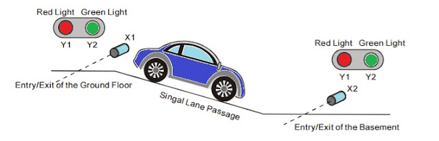
Basic PLC Ladder Programming Examples 19 Basic PLC Ladder Programming Training Examples for Beginners.  Hi friends, here we are starting unique a series of Free Training on PLC Ladder Programming & tutorials. These PLC Ladder Programs are important to learn basics of Ladder programs.   PLC Ladder Practice Problem:  Entry/Exit Control of the Underground Car Park. ·        The entry/exit of the underground car park is a single lane passage which needs the traffic lights to control the cars. Red lights prohibit cars entering or leaving while green lights allow cars to enter or leave. ·        When a car enters the passage from the entry of the ground floor, the red lights both on the ground floor and the basement will be ON, and the green lights will be OFF. Any car entering or leaving is prohibited during the process till the car passes through the passage completely. When the passage is clear...

PIC16F887 877 programming in C Tutorial 3 1 Timer 0

Image
Timers Both PIC16f887 and 877 have three timers; timer 0, timer 1, and timer 2. Timer 0 is 8-bit and can also be use as counter, Timer 1 is 16-bit timer as well as a counter, where as Timer 2 is 8-bit timer and can be used as the PWM time base for the PWM mode of the CCP module(s).  Timer 0: The Timer0 module timer/counter has the following features: 8-bit timer/counter Readable and writable 8-bit software programmable prescaler Internal or external clock select Interrupt on overflow from FFh to 00h Edge select (rising or falling) for external clock Timer mode is selected by clearing bit T0CS (OPTION_REG<5>). In Timer mode, the Timer0 module will increment every instruction cycle (without prescaler). Counter mode is selected by setting bit T0CS (OPTION_REG<5>). In Counter mode, Timer0 will increment either on every rising or falling edge of pin RA4/T0CKI. The incrementing edge is determined by the Timer0 Source Edge Select bit, T0SE (OPTION_REG<4>). Clearing bit T...