Posts

Showing posts with the label Supply

How to Build Unregulated Linear Power Supply
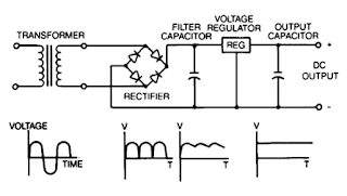
Image
Unregulated power supplies contain four basic components: transformer, rectifier, filter capacitor, and a bleeder resistor. This type of power supply, because of Us simpticity, is the least costly and most reliable for low power requirements. The disadvantage is that the output voltage is not constant It will vary with the input voltage and the load current, and the ripple is not suitable for electronic applications. The ripple can be reduced by changing the filter capacitor to an LC (inductor-capacitor) filter but the cost to make this change would make use of the regulated linear power supply a more economical choice.

6A 0 28V Variable Power Supply

Image
Components List: R1 = 2K2 Ohm 2,5 Watt R2 = 240 Ohm R3,R4 = 0.1 Ohm 10 Watt R7 = 6K8 Ohm R8 = 10K Ohm R9 = 47 Ohm 0.5 Watt R10 = 8K2 Ohm C1, C7, C9 = 47nF C2 = 4700uF/50v – 6800uF/50v C3, C5 = 10uF/50v C4, C6 = 100nF C8 = 330uF/50v C10 = 1uF/16v C11 = 22nF D1…D4 = four MR750 (MR7510) diodes (MR750 = 6 Ampere diode) or 2 x 4 1N5401 (1N5408) diodes. D5 = 1N4148, 1N4448, 1N4151 D6 = 1N4001 D10 = 1N5401 D11 = LED D7, D8, D9 = 1N4001 TR = 2 x 15 volt (30volt total) 6+- Ampere IC1 = LM317 T1, T2 = 2N3055 P1 = 5k P2 = 47 Ohm or 220 Ohm 1 Watt P3 = 10k trimmer F1 = 1 Amp F2 = 10 amp Circuit Description: This is an easy to make power supply that has reliable, clear and regulator 0 to 28 Volt 6/8 Amp output voltage. By making use of two 2N3055 transistor, you’ll get two times the amount of electric current. Although the 7815 power regulator may kick in on short circuit, overload and thermal overheating, the fuses in the main section of the transformer and the fuse F2 at the output will safe yo...

Adjustable Symmetrical Power Supply Using LM317 and LM337

Image
The circuit was designed to provide an adjustment with a power supply that is symmetrically designed while providing a voltage range of 1.25V to 30V at 1A current. LM317 – an adjustable 3-terminal positive voltage regulator capable of supplying in excess of 1.5A over an output voltage range of 1.2V to 37V and requires only two external resistors to set the output voltage due to its internal current limiting, thermal shutdown and safe area compensation, making it essentially blow-out proof LM337 – an adjustable 3-terminal positive voltage regulator capable of supplying in excess of 5A used as battery chargers, constant current regulators, and adjustable power supplies due to its features such as protected output from short circuit, product enhancement tested, current limit constant with temperature, guaranteed thermal regulation, adjustable output down to 1.2V, guaranteed 5A, and guaranteed 7A peak output current. The circuit will serve as a voltage converter with an input voltage of 35...

Power Supply Failure Alarm

Image
Most of the power supply failure indicator circuits need a separate power-supply for them-selves. But the alarm circuit presented here needs no additional supply source. It employs an electrolytic capacitor to store adequate charge, to feed power to the alarm circuit which sounds an alarm for a reasonable duration when the mains supply fails. During the presence of mains power supply, the rectified mains voltage is stepped down to a required low level. Power Supply Failure Alarm Circuit Diagram: A zener is used to limit the filtered voltage to 15-volt level. Mains presence is indicated by an LED. The low-level DC is used for charging capacitor C3 and reverse biasing switching transistor T1. Thus, transistor T1 remains cut-off as long as the mains supply is present. As soon as the mains power fails, the charge stored in the capacitor acts as a power-supply source for transistor T1. Since, in the absence of mains supply, the base of transistor is pulled ‘low’ via resistor R8, it conduct...

Adjustable Symmetrical Power Supply Using LM317 and LM337

Image
The circuit was designed to provide an adjustment with a power supply that is symmetrically designed while providing a voltage range of 1.25V to 30V at 1A current. LM317 – an adjustable 3-terminal positive voltage regulator capable of supplying in excess of 1.5A over an output voltage range of 1.2V to 37V and requires only two external resistors to set the output voltage due to its internal current limiting, thermal shutdown and safe area compensation, making it essentially blow-out proof LM337 – an adjustable 3-terminal positive voltage regulator capable of supplying in excess of 5A used as battery chargers, constant current regulators, and adjustable power supplies due to its features such as protected output from short circuit, product enhancement tested, current limit constant with temperature, guaranteed thermal regulation, adjustable output down to 1.2V, guaranteed 5A, and guaranteed 7A peak output current. The circuit will serve as a voltage converter with an input voltage of 35...

6 to 12 Volt Power Supply Inverter

Image
This inverter circuit can provide up to 800mA of 12V power from a 6V supply. For example, you could run 12V car accessories in a 6V (British?) car. The circuit is simple, about 75% efficient and quite useful. By changing just a few components, you can also modify it for different voltages. Part List: R1, R4 2.2K 1/4W Resistor R2, R3 4.7K 1/4W Resistor R5 1K 1/4W Resistor R6 1.5K 1/4W Resistor R7 33K 1/4W Resistor R8 10K 1/4W Resistor C1,C2 0.1uF Ceramic Disc Capacitor C3 470uF 25V Electrolytic Capcitor D1 1N914 Diode D2 1N4004 Diode D3 12V 400mW Zener Diode Q1, Q2, Q4 BC547 NPN Transistor Q3 BD679 NPN Transistor L1 See Notes MISC Heatsink For Q3, Binding Posts (For Input/Output), Wire, Board source:LINK

Variable Adjustable DC Power Supply 1 2V – 25V using LM338K

Image
                                    This is variable DC power supply circuit, or we can call it adjustable DC power supply which give us a 1.2V-25V output voltage. The power supply schematic above is taken from the datasheet of regulator LM338K manufactured National Semiconductor. The circuit uses IC LM338K as the voltage regulator, so we will get the stable and regulated output. The regulator IC LM338K provides 5A output current max, and the voltage from 1.2 to 32V, it also featured the integrated thermal and short-circuit protection. Maximum voltage at input and output of the regulator is 35V . The transformer current value depends your needs. For example, if you need 120W power output then you’ll need 5A transformer. 5A x 24V (full power) will give you 120W output power. Since this power supply circuit described to give us 1.2-25V DC output, then you must have transformer with 24V AC output. Fo...

Simple 12V Portable and Mobile Power Supply Schematic

Image
This is the Simple 12V Portable and Mobile Power Supply Schematic .This type of power supply can be built quite inexpensively and needs only a minimum of circuitry. This circuit will give output current of 1 amp, well stabilized and smoothed. Simple 12V Portable and Mobile Power Supply Schematic The smoothing and regulation is provided by IC1 7812 which is a 12V monolithic voltage regulator. Thisportable power supplyunit incorporates output current limiting and is therefore not damaged by accidental short term short circuits or other forms of output overloading.   components Resistor1/3 watt 5% R1 1.8k Capacitors Cl 2200uF 25V electrolytic C2 100nF polyester (C280) C3 100nF polyester (C280) Semiconductors ICI uA78I2 (12 volt 1 amp positive regulator) D1 to D4 1N4002(4 off) Switch S1 DPST toggle type Transformer T1 Standard mains primary, 15 — 0 — 15 volt 2 amp secondary

9V Battery Replacement Power Supply

Image
This circuit was originally designed to power a motorcycle intercom from the vehicle supply system. This type of intercom, which is used for communication between driver and passenger, generally requires quite a bit of power. In order to improve intelligibility there is often elaborate filtering and a compander is sometimes used as well. The disadvantage is that a battery doesn’t last very long. You could use rechargeable batteries, of course, but that is often rather laborious. It seems much more obvious to use the motorcycle power supply instead. A 9-V converter for such an application has to meet a few special requirements. For one, it has to prevent interference from, for example, the ignition system reaching the attached circuit. It is also preferable that the entire circuit fits in the 9-V battery compartment. This circuit meets these requirements quite successfully and the design has nonetheless remained fairly simple. In the schematic we can recognize a filter, followed by a vo...

Hannspree AT06 42 inch LCD TV Power Supply board – Schematic 715T2512 2 China SMPS

Image

Variable 5 to 20V DC Supply Circuit Diagram

Image
If you are looking for a low drop voltage regulator that can provide a power supply of 1A with an output voltage of between 5V and 20V DC, National Semiconductor LM2941 Low Dropout Adjustable Regulator is that you can pick to make use of. It's a typical dropout voltage of 0.5V which means that the input supply need only must be 0.5V DC over the desired output voltage. Its other features include internal short circuit current limit and reverse battery protection. As shown in the schematic below, the regulator has five pins which consists of the ON/OFF control, Input Voltage, Output Voltage, Ground & Adjustable pins. ON/OFF is used for the purpose of switching on & off of the regulator. The capacitors C1 & E1 are to be placed as close as feasible to the regulator. The output of the circuit can be varied by varying the worth of potentiometer VR1 from 5V DC to 20V DC. The input voltage is limited from five.5V DC to 30V DC. Resistor R1 must be greater than 1K. The worth of t...

12V 3A Power Supply Circuit Diagram

Image
This circuit provides a 12V regu-lated power supply with output current up to 3 amperes. It is spe-cially designed for use with 2m handheld rigs with linear power amplifier and CB portable QRP rigs. The circuit uses monolithic IC CA3085 voltage regulator in 8-lead TO-5 package.  Its salient features include good load and line regulation, output current up to 100 mA (which can be increased to several amperes with additional pass transistors), output short-circuit protection, and lower input voltage.  A low power dissipation is achieved by driving external series-pass transistor 2N4241 (T1) from  pin 2 of CA3085. Circuit diagram :   12V, 3A Power Supply Circuit Diagram Normal output pin 8 is returned to ground via diodes D3 and D4 to ensure error am-plification operation in the linear region. Ripple rejection is approximately 50 dB on no load and 35 dB on full load.  A 2x2x2.5cm aluminium heat sink fas-tened onto a 1.5mm blackened aluminium sheet of 12.5cm2 are...

Simple 30V Variable Power Supply Using LM317

Image
This 30v variable power supply circuit is based on LM317   voltage regulator circuit . This LM317 30v variable power supply circuit can deliver high current (around 5 amps) and variable output voltage between 1.2 volts, up to 30 volts. The led D3 mounted on pin 6 at lm301 lights in constant current mode . Circuit diagram  Current limit can be adjusted using R2 potentiometer and the output voltage can be adjusted from 1.2 volts to 30 volts using R8 potentiometer . Input voltage for this variable power supply must be around 35 volts .For this power supply circuit you need to use LM317K circuit (in to3 package ) which must be mounted on a heatsink .

REGULATED POWER SUPPLY

Image
INTRODUCTION A regulated power supply is an embedded circuit, or stand alone unit, the function of which is to supply a stable voltage (or less often current), to a circuit or device that must be operated within certain power supply limits. The output from the regulated power supply may be alternating or unidirectional, but is nearly always DC. COMPONENTS   REQUIRED 1. STEP DOWN TRANSFORMER (12-0-12 type) 2. 78XX SERIES IC (e.g. 7805,7808,7809…etc as per requirement) 3. CAPACITORS (1X 470 uf, 2x .1uf) 4. DIODES (4X 1N4001 or 1N4007) 5. 1A FUSE Circuit Diagram Here is the circuit diagram of our regulated power supply   You can use IC7805 for constant 5v DC supply, IC7808 FOR 8V, IC7809 FOR 9V and so on. There are four stages in this circuit- 1. TRANSFORMER to step down AC supply within the range of around 12 v. 2. A BRIDGE RECTIFIER is used for rectification purpose. 3. in SMOOTHING stage AC ripples are removed by the help of capacitor used. 4. in REGULATOR s...

0 24VDC Digital PIC Power Supply

Image
This is 0-24VDC digital PIC power supply circuit. This variable power supply controlled with PIC microcontroller. There is LCD display in this circuit which will show the actual value of power supply output. This power supply use push on switch to adjust the output voltage and current value. Schematic Diagram: Component List : C1 = 2000uF per AMP, 40V (adjust capacity to power supply amps) C2,C3,C12,C15,C18,C21 = 0.1uF CER C4 = 0.01uF CER C5A,C5B,C5C,C5D = 0.01uF CER C6,C7 = 0.05uF CER C8 = Not used C9,C11,C19,C20 = 1uF CER C10 = 470uF 15V EL RADIAL C13 = 4.7µF 50V EL RADIAL C14 = 0.001uF CER C16,C17 = 22pF CER D1,D2,D4,D5 = 1N4148 D3 = 1N4004 Br1 = 1<10A BRIDGE RECTIFIER (adjust seize to power supply amps) DZ1 = 1N4751 30V ZENER IC1 = LM317KCS TO220 IC2 = LM337LZ TO92 IC3 = LT1491CN special HV opamp, do not substitute IC4 = PIC16F876A Q1 = 2N3906 Q2A to Q2D = TIP142TU 1 to 5 transistors (adjust quantity to power supply amps) Q3A to Q3D = 2N3904 (adjust quantity to power supply am...

Power Supply with High Voltage Isolation Circuit Diagram

Image
Power Supply with High Voltage Isolation Circuit Diagram . Occasionally you come across some unusual  situations when setting up measurement  systems. The author once had to set up a system to register the vibrations and strain supposed to be  present in a contractor that operated at a voltage of 25 kVAC. One of the biggest problems with this project turned out to be the power supply for  the measurement system. Since it required  a power of about 30 W it wasn’t possible to  use batteries since the system had to operate  for many hours at a time. A logical solution  would seem to be to use an isolating trans-former, but still.25 kVAC means a peak volt-age approaching 40 kV, and on top of that  you would have to include a safety margin. In  addition, everything that is connected to high  voltage lines should also be able to withstand  lighting strikes! . Circuit diagram : Power Supply with High Voltage Isolation Circuit Diagra...

30 VDC Stabilized power supply with current control 0 002 3 A

Image
  General Description This is a high quality power supply with a continuously variable stabilised output adjustable at any value between 0 and 30VDC. The circuit also incorporates an electronic output current limiter that effectively controls the output current from a few milliamperes (2 mA) to the maximum output of three amperes that the circuit can deliver. This feature makes this power supply indispensable in the experimenters laboratory as it is possible to limit the current to the typical maximum that a circuit under test may require, and power it up then, without any fear that it may be damaged if something goes wrong. There is also a visual indication that the current limiter is in operation so that you can see at a glance that your circuit is exceeding or not its preset limits.     Technical Specifications - Characteristics Input Voltage: ................ 24 VAC Input Current: ................ 3 A (max) Output Voltage: ............. 0-30 V adjustable Outp...

6 to 12 Volt Power Supply Inverter

Image
This inverter circuit can provide up to 800mA of 12V power from a 6V supply. For example, you could run 12V car accessories in a 6V (British?) car. The circuit is simple, about 75% efficient and quite useful. By changing just a few components, you can also modify it for different voltages. Part List: R1, R4 2.2K 1/4W Resistor R2, R3 4.7K 1/4W Resistor R5 1K 1/4W Resistor R6 1.5K 1/4W Resistor R7 33K 1/4W Resistor R8 10K 1/4W Resistor C1,C2 0.1uF Ceramic Disc Capacitor C3 470uF 25V Electrolytic Capcitor D1 1N914 Diode D2 1N4004 Diode D3 12V 400mW Zener Diode Q1, Q2, Q4 BC547 NPN Transistor Q3 BD679 NPN Transistor L1 See Notes MISC Heatsink For Q3, Binding Posts (For Input/Output), Wire, Board source:LINK

6 to 12 Volt Power Supply Inverter

Image
This inverter circuit can provide up to 800mA of 12V power from a 6V supply. For example, you could run 12V car accessories in a 6V (British?) car. The circuit is simple, about 75% efficient and quite useful. By changing just a few components, you can also modify it for different voltages. Part List: R1, R4 2.2K 1/4W Resistor R2, R3 4.7K 1/4W Resistor R5 1K 1/4W Resistor R6 1.5K 1/4W Resistor R7 33K 1/4W Resistor R8 10K 1/4W Resistor C1,C2 0.1uF Ceramic Disc Capacitor C3 470uF 25V Electrolytic Capcitor D1 1N914 Diode D2 1N4004 Diode D3 12V 400mW Zener Diode Q1, Q2, Q4 BC547 NPN Transistor Q3 BD679 NPN Transistor L1 See Notes MISC Heatsink For Q3, Binding Posts (For Input/Output), Wire, Board source:LINK

Adjustable Power Supply 0 15V 5A Circuit Diagram

Image
This is the simple Simple Adjustable Power Supply 0-15V / 5A Circuit Diagram. This adapted ability accumulation can be adapted amid a few volts and 15V with P1 and with P2 acclimatize the high absolute ( 15.0V ). R6 amount is 0.7V / Imax area Imax is the best current. At Imax = 5A, R6 is 0.14Ω Simple Adjustable Power Supply 0-15V / 5A Circuit Diagram T1 and T2 charge accept heatsinks because ability losses are abundant at a low achievement voltage and a Imax according accepted but you can affix the lamp L to abate this losses. I’ve body this adjustable ability accumulation and works great! I achievement you’ll adore it too and accept fun body this abundant counterbalanced ability supply