Posts

Showing posts with the label Automatic

Automatic Low Power Emergancy Light Circuit diagram

Image
Here is a white-LED-based emergency light that offers the following advantages. 1-It is highly bright due to the use of white LEDs. 2-The light turns on automatically when mains supply fails, and turns off when mains power resumes. 3-It has its own battery charger. When the battery is fully charged, charging stops automatically. The charger power supply section is built around 3-terminal adjustable regulator IC LM317 (IC1), while the LED driver section is built around transistor BD140 (Q2). In the charger power supply section, an input AC main is stepped down by T1 to deliver 9V, 500mA to the bridge rectifier, which comprises diodes D1 through D4. Filter capacitor C1 eliminates ripples. Unregulated DC voltage is fed to input pin 3 of IC1 and provides charging current through D5 and limiting resistor R15. By adjusting preset P1, the output voltage can be adjusted to deliver the required charging current. When the battery gets charged to 6.8V, D6 conducts and charging current from IC1 fi...

Automatic 9 volt Battery Charger Circuit Diagram

Image
Good care given to your NiCad batteries will ensure a long life. However, they do need to be handled and charged with special care. It is therefore important to first discharge the NiCad to 1 Volt per cell, ensure that the battery is discharged, and then start the charge cycle. recommend a charge current of 1/10th the capacity for a duration of about 15 hours uninterrupted. In reality, we learn some hard lessons when we forget to switch the charger off after the 15 hours and find that one or more cells inside the battery no longer accept a charge. That is the very reason that the circuit above is fully automated. The only thing to do is connect the battery and press the 'Start' button. When the discharge cycle is finished the circuit switches over to charge for 15 hours. After the 15 hours the circuits maintains a trickle charge to keep the battery 'topped-up Automatic 9-volt Battery Charger Circuit Diagram Before I go into the schematic details I like to explain some of th...

Simple B C with Automatic Switch off Circuit Diagram

Image
This is a Simple Battery Charger with Automatic Switch-off Circuit Diagram . This lovely charger automatically switches off when your rechargeable batteries reach the full charge.The circuit comprises a bistable multivibrator wired around timer IC 555. The bistable output is fed to an ammeter (via diode D1) and pot meter VR1 before it goes to three Ni-Cd batteries that are to be charged. Battery Charger with Automatic Switch-off Circuit Diagram Normally, the full charge potential of an Ni-Cd cell is 1.2V. Trigger the bistable by pressing switch S1 and adjust potmeter VR1 for 60mA current through the ammeter. Now remove the ammeter and connect a jumper wire between its points ‘a’ and ‘b.’ Connect the positive output terminal of the batteries to the emitter of pnp transistor T1. The base of transistor T1 is held at 2.9V by adjusting potmeter VR2. The output of transistor T1 is inverted twice by npn transistors T2 and T3. Thus when the batteries are fully charged to 3×1.2V=3.6V, a voltag...

SP Semi Automatic Paintbrush

Image
Got a replacement InkShield and progressing to build an Open hardware project? Then why not strive creating the Semi-Automatic Paintbrush. browse on to grasp a lot of concerning this. Any work of art are often copied using this and therefore the elements that are needed to form this is often listed below: IR camera InkShield Ink cartridge IR LED. The software that's run on a desktop for this purpose is understood as paintbrush.py. The software plays the role of mapping the camera focus with the co-ordinate system of the canvas. Four LEDs are placed at every corner of the canvas and therefore the mapping is calibrated by hitting a key when needed. The region of the image is captured by tracking the motion of the LEDs. the mandatory commands are send to an Arduino with the InkShield by means that of a script written for this purpose. The script tells the arduino that nozzle to fireplace and additionally the grey level that must be achieved by the firing nozzle. so as to avoid floodin...

Delayed Automatic Forward Reverse Motion of Overhead Crane Driven by a Motor

Image
This is another situation that requires the overhead crane to rest for a while  upon reaching both of the rail. After a pre-determine time the overhead crane  will re-start in the opposite direction. Control circuit of "Delay Automatic Forward Reverse Motor of an Overhead Crane" The control circuit of this system is shown Above. Two times TR1 and TR2 are connected to the limit switches Y and X respectively at terminal 3. The terminal no. 1 of the instantaneous contacts TR1(1-3) and TR2(1-3) are connected to the terminals no. 3 of the limit switch Y and X respectively. The delay contact TR1(6-8) and TR2(6-8) are connected to the contacts R(13-14) and F(13-14) respectively. Supposing the overhead crane is moving in the forward (right) direction that means, contactor F(A-B) is at energized and contactor R(A-b) is at de-energize condition. When the overhead crane reaches the right end limit and touches the limit switch Y, the contact Y(1-2) of limit switch Y will open to de-energ...

Automatic 6 volt 12 volt 24 volt Lead Acid Battery Charger

Image
A simple yet accurate automatic, regulated 6/12/24 volt lead acid battery charger circuit is explained in this article. The circuit switches off the current to the battery as soon as the battery reaches full charge. An illuminated LED at the output indiacates the fully charged condition of the battery. The circuit diagram may be understood from the following points: Fundamentally the voltage control and regulation is done by the versatile, work horse IC LM 338. An input DC supply volt in the range of 30 is applied to the input of the IC. The voltage may be derived from a transformer, bridge and capacitor network. The value of the 47k  preset is set to get the required output voltage, depending upon the battery voltage to be charged. If a 6 volt battery needs to charged, R2 is selected to produce a voltage of around 7 volts at the output, for a 12 volt battery it becomes 14 volts and for a 24 volt battery, the setting is done at around 28 volts. The above settings take ...

Simple Automatic Switch For Audio Power Amplifier

Image
Circuit of an automatic switch for audio power amplifier stage is presented here. The circuit uses stereo preamplifier output to detect the presence of audio to switch the audio power amplifier on only when audio is present. The circuit thus helps curtail power wastage. IC1 is used as an inverting adder. The input signals from left and right channels are combined to form a common signal for IC2, which is used as an open loop comparator. IC3 (NE556) is a dual timer. Its second section, i.e., IC3(b), is configured as monostable multivibrator. Output of IC3(b) is used to switch the power amplifier on or off through a Darlington pair formed by transistors T1 and T2. IC3(a) is used to trigger the monostable multivibrator whenever an input signal is sensed. Circuit diagram: Automatic Switch For Audio Power Amplifier Circuit Diagram Under ‘no signal’ condition, pin 3 of IC2 is negative with respect to its pin 2. Hence the output of IC2 is low and as a result output of IC3(a) is high....

New Automatic Load Sensing Power Switch

Image
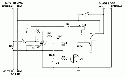
This circuit will automatically switch on several mains-powered "slave" loads when a "master" load is turned on. For example, it will switch on the amplifier and CD player in a stereo system when the receiver is turned on. It works by sensing the current draw of the "master" device through a low value high wattage resistor using a comparator. The output of that comparator then switches on the "slave" relay. The circuit can be built into a power bar, extension cord or power center to provide a convenient set of "smart" outlets that switch on when the master appliance is powered (turn on the computer monitor and the computer, printer and other peripherals come on as well). New Automatic Load Sensing Power Switch Circuit Diagram Parts Part               Total Qty. Description C1, C3               2              ...

Automatic Bike Headlight Switch

Image
Improved bike headlight switch circuit presented here has been designed to switch bike headlight on (or similar loads) at a presettable ambient light level. The circuit is based on the renowned timer chip LM555 (IC1), here triggered by a decrement in ambient light level. Here is a 220V automatic light switch, just in case you need one. how does the automatic headlight switch works? When 12VDC supply is applied to the circuit, the voltage at pin 2 of IC1 is set by the voltage divider built around the Light Dependent Resistor (LDR) and trimpot P1 (100K). If the ambient light level (presetted by P1) is sufficient, pin 2 of IC1 is at a high potential and as a result IC1 is disabled. Capacitor C1 (100uF/25V) added across the LDR eliminates possible unwanted circuit functioning which may caused by sudden fluctuations in the light level. However, when ambient light level drops, the resistance of LDR increases and the voltage level at pin 2 of IC1 drops to trigger the monostable circuit. Simu...

Automatic Night Light using Phototransistor

Image
Here is the simple Automatic Night Light circuit using Phototransistor. Components Required: 1) Breadboard 2) 470 ohm resistor 3) 22 Kilo ohm resistor 4) LED (Any Color) 5) Phototransistor 6) 3904 NPN Transistor 6) 9Volt Battery  Procedure: Connect the circuit as shown in the circuit diagram below. During day time the brightness will be more, which forward biases the phototransistor. Therefore the current flows through the collector to emitter of phototransistor. Hence there is no base current to forward bias the 3904 NPN transistor and the LED remains OFF. During night time the brightness goes down, which cannot forward bias the phototransistor. Therefore the current will not flow through the phototransistor. Hence there is enough base current to forward bias the 3904 NPN Transistor and the LED glows. Circuit Diagram: Figure 1: Automatic Night Light using Phototransistor Circuit simulation made in Multisim Figure 2: Automatic Night Light using Phototransistor

Automatic Water Pump Controller Circuit

Image
Automatic water pump controller is a series of functions to control the Automatic Water Pump Controller Circuit in a reservoir or water storage. As the water level sensor made with a metal plate mounted on the reservoir or water tank, with a sensor in the short to create the top level and a detection sensor for detecting long again made the lower level and ground lines connected to the bottom of reservoirs or reservoir. The series of automatic water pump controller is designed with 2 inputs NOR by 4 pieces and relay that is activated by the transistor. Automatic water pump circuit requires +12 VDC voltage source and can be used to control the water pump is connected to AC power . Here is the complete series of pictures. Series Automatic Water Pump Controller  List Component Automatic Water Pump Controller  R1 = 15K  R2 = 15K  R3 = 10K  R4 = 1K  D1 = LED  D2 = 1N4148  Q1 = BC337  IC1 = 4001  SW = SPDT Switches  Relay RL1 = 12V...

Simple Automatic Load Sensing Power Switch

Image
This circuit will automatically switch on several mains-powered "slave" loads when a "master" load is turned on. For example, it will switch on the amplifier and CD player in a stereo system when the receiver is turned on. It works by sensing the current draw of the "master" device through a low value high wattage resistor using a comparator. The output of that comparator then switches on the "slave" relay. The circuit can be built into a power bar, extension cord or power center to provide a convenient set of "smart" outlets that switch on when the master appliance is powered (turn on the computer monitor and the computer, printer and other peripherals come on as well). .  Simple Automatic Load Sensing Power Switch Circuit Diagram Parts Part               Total Qty. Description C1, C3               2            ...

Automatic TV Lighting Switch Circuit Diagram

Image
Automatic TV Lighting Switch . The author is the happy owner of a television set with built-in Ambilight lighting in the living room. Unfortunately, the television set in  the bedroom lacks this feature. To make up for this, the author attached a small lamp to the wall to provide background lighting, This makes  watching television a good deal more enjoyable, but it ’s  not the ideal solution. Although the TV set can be  switched off with the remote  control, you still have to get out of bed to switch off the lamp. Automatic TV Lighting Switch Circuit diagram Automatic TV Lighting Switch Circuit Diagram Consequently, the author devised this automatic lighting switch that switches the background light on and off along with the T V set. The entire circuit is fitted in series with the mains cable of the TV set, so there’s no need to tinker with the set. It works as follows: R1 senses  the current drawn by the TV  set. It has a maximum value  of 50 m...

Automatic Fuse Circuit

Image
To restrict / security, electric current is usually used fuse or patron is dissolved when going short will drop out and must be replaced with a new one. Then, in order not to drop out of each new change means that more money out to buy, then there fuse automatically work with the reset button. So there are problems with each short, fuse will automatic decided flow then to return it does not need to buy a new (if not broken) just press the reset the equipment will live again. Circuit Diagram   Automatic Fuse Circuit  is one of the simplest electronic fuse circuit one can make. The circuit uses only one transistor, one SCR, one push button switch and two resistors. The value of R1 can be obtained from the equation; [Imax] X [R1] = 0.7V. R2 can be obtained from the equation; R2 = [Vs] X [1K Ohms]. Wattage rating of R1 can be obtained from the equation; W = [Imax] X [Imax] X [R1]. For this circuit to work the current consumption of the load must be greater than the holding curr...