Posts

Showing posts with the label Watt

LM1875 – POWER AMPLIFIER 20 WATT CIRCUIT dIAGRAM

Image
The LM1875 is a monolithic power amplifier offering very low distortion and high quality performance for consumer audio applications. The LM1875 delivers 20 watts into a 4Ω or 8Ω load on ±25V supplies. Using an 8 load and ±30V supplies, over 30 watts of power may be delivered. The amplifier is designed to operate with a minimum of external components. Device overload protection consists of both internal current limit and thermal shutdown. The LM1875 design takes advantage of advanced circuit techniques and processing to achieve extremely low distortion levels even at high output power levels. Other outstanding features include high gain, fast slew rate and a wide power bandwidth, large output voltage swing, high current capability, and a very wide supply range. The amplifier is internally compensated and stable for gains of 10 or greater. Features • Up to 30 watts output power • AVO typically 90 dB • Low distortion: 0.015%, 1 kHz, 20 W • Wide power bandwidth: 70 kHz • Protection for A...

Simple 1 Watt PLL FM Broadcast Transmitter

Image
To day i share a little power for my friends.This is a Simple 1 Watt PLL FM Broadcast Transmitter . The RF output varies from 500mW to about 1.2W depending on the frequency selected and RF output transistor used. Motorola 2N4427 always seems to work well. Transmitter uses CMOS PLL VCO that prevents the frequency drifts. The frequency is selected via DIP switches. The transmitter is supplied by 12V DC and can also be powered from the battery.   Simple 1 Watt PLL FM Broadcast Transmitter

5 Watt Class A Audio Amplifier Circuit Diagram

Image
This solid-state push-pull single-ended Class A circuit is capable of providing a sound comparable to those valve amplifiers, delivering more output power (6.9W measured across a 8 Ohm loudspeaker cabinet load), less THD, higher input sensitivity and better linearity. Voltage and current required for this circuit are 24V and 700mA respectively, compared to 250V HT rail and 1A @ 6.3V filament heating for valve-operated amplifiers. The only penalty for the transistor operated circuit is the necessity of using a rather large Heatsink for Q2 and Q3 (compared to the maximum power delivered).In any case, the amount of heat generated by this circuit can be comparable to that of a one-valve amplifier. An optional bass-boost facility can be added, by means of R5 and C5.   Circuit diagram: Parts: P1 = 47K R1 = 100K R2 = 12K R3 = 47K R4 = 8.2K R5 = 1.5K R6 = 2.7K R7 = 100R R8 = 100R R9 = 560R-1/2W R10 = 1R-1/2W Q1 = BC560 Q2 = BD439 Q3 = BD439 C1 = 10uF-63V C2 = 10uF-63V C3 = 47uF-25V C4 = 10...

1 Watt PLL FM Broadcast Transmitter Circuit

Image
To day i share a little power for my friends.This is a Simple 1 Watt PLL FM Broadcast Transmitter. The RF output varies from 500mW to about 1.2W depending on the frequency selected and RF output transistor used. Motorola 2N4427 always seems to work well. Transmitter uses CMOS PLL VCO that prevents the frequency drifts. The frequency is selected via DIP switches. The transmitter is supplied by 12V DC and can also be powered from the battery.   Simple 1 Watt PLL FM Broadcast Transmitter

Inverter 5000 Watt PWM Circuit Diagram

Image
This is a simple Inverter 5000 Watt PWM Circuit Diagram . This inverter uses PWM (Pulse Width Modulator) with type IC SG3524. IC serves as a oscillator 50Hz, as a regulator of the desired output voltage. Input power ranging from 250W up to 5000W output and has. Following a series INVERTER 5000W with PWM (Pulse Width Modulator).   Inverter 5000 Watt PWM Circuit Diagram Pcb Layout Below is the output power settings that can be issued by this inverter: DC voltage and Transformer "T2" winding recommendation: Winding Power Supply 12VDC 750W P: 24V "12-0-12" / S: 220V 1500W 24VDC P: 48V "24-0-24" / S: 220V 2250w 36VDC P: 72V "36-0-36" / S: 220V 3000w 48VDC P: 96V "48-0-48" / S: 220V 3750w 60VDC P: 120V "60-0-60" / S: 220V 4500w 72VDC P: 144V "72-0-72" / S: 220V 5250w 84VDC P: 168V "84-0-84" / S: 220V Transformer used is the transformer CT R1 serves to regulate the voltage to 220v inverter R2 serves to regulate ...

100 Watt Power Amplifier Circuit With IC TDA7294

Image
Power Amplifier TDA7294 is a power amplifier with IC Power Amplifier is a mono 100W Class AB operation of OCL. The power supply circuit. Positive, negative, and ground. Usually, we use the power supply circuit to + /-25V to + /-35V at 100W RMS will be used to heat sufficiently. After many members have already made the TDA7294 as I know, with a sound quality that is the very gods or Hi-End itself. Several days before the member’s PM to me saying that I had an amplifier using IC TDA7294 to have more of the same. Higher power. And low heat. Achieved by increasing the voltage raising circuit For the more, it means high power and high heat up. Today I have come across. I use IC TDA7294 circuit at the time. In-Home Use amplifier circuit is a Class G amplifier with low power consumption, resulting in the loss of a 20V DC power less. And when you’re driving a high-power random access is party to a rhythm. Principles to do it. I took out a membership you ...

Single Chip 25 Watt Mono Class D Audio Power Amplifier Circuit

Image
This class-D audio ability amplifier is acceptable for TV and home stereo set. TDA7882 IC dent provides class-D audio ability amplifier solution. Since this dent has alone address channel, you charge two pieces of this ambit for stereo application. The ability accumulation voltage is flexible, acquire (+-)10V to (+-)25V. This ambit needs a breach accumulation (symmetric ability supply). Here are the capital appearance of this class-D amplifier: 25W OUTPUT POWER: RL = 8 ohm/4 ohm; THD = 10% HIGH EFFICIENCY WIDE SUPPLY VOLTAGE RANGE (UP TO ±25V) SPLIT SUPPLY OVER-VOLTAGE PROTECTION ST-BY AND MUTE FEATURES SHORT CIRCUIT PROTECTION THERMAL OVERLOAD PROTECTION

4 x 35 Watt car audio amplifier

Image
General Description: The AN7560Z is an audio power IC developed as the sound output of car audio (35 W by 4-ch.). A capacitor and resisitor to stop oscillation are built in between the output pin and GND so that a space saving of set is possible. Also, it incorporates a perfect muting circuit with out shock noise so that a shock noise design under the set transient condition can be made easily when used together with its standby function. In addition, it incorporates various protection circuits to protect the IC from destruction by GND-open-shortcircuit to ground and power supply surge which are the important subject of power IC protection. This IC will largely contribute to a high reliability design of the equipment. Circuit Diagram: 4 x 35 Watt car audio amplifier Datasheet for AN7560:  Download

3 Watt power amplifier schematic

Image
This time I will share a circuit of schematis power amplifier with LM380 IC that has similarities with LM384. Enough with just a few components you have to make this power amplifier circuit . All components with relatively low prices and making a fairly easy. For this amplifier output power has 3W with 4 ohm impedance. Indeed , this amplifier has the output is quite low and certainly will not be maximal if it works on the speakers with high power. Component List : Resistor R1______________47K R2______________2.7R 2W Capacitor C1______________10uF C2______________470uF C3______________100n C4______________100n IC IC1_____________LM380 , LM384

230 400 Watt Power Amplifier MOSFET

Image
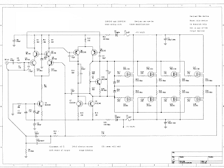
Amplifier circuit below is a series of amplifiers with the amplifier transistor and mosfet. This amplifier output power ranging from 230W up to 400W. 230 - 400 Watt Power Amplifier

House fm transmitter 88 108MHz at 4 Watt

Image
This is Fm transmitter circuit for house. It is modulation type Mono FM and Frequency range 88-108 MHz. By it have Working voltage range 12-18 VDC and use current max at 450mA only. This circuit convenient for , because , have good small-sized. It is the ideal project for the beginner who wishes to get started in the fascinating world of FM broadcasting and wants a good basic circuit. This circuit use the transistor the important , be the number is 2N3553.

18 Watt Audio Amplifier circuit diagram

Image
18 Watt Audio Amplifier circuit diagram Amplifier parts: P1____22K Log. Potentiometer (Dual-gang for stereo) R1___1K 1/4W Resistor R2___4K7 1/4W Resistor R3___100R 1/4W Resistor R4___4K7 1/4W Resistor R5___82K 1/4W Resistor R6___10R 1/2W Resistor R7___R22 4W Resistor (wirewound) R8___1K 1/2W Trimmer Cermet (optional) C1___470nF 63V Polyester Capacitor C2,C5___100µF 3V Tantalum bead Capacitors C3,C4___470µF 25V Electrolytic Capacitors C6___100nF 63V Polyester Capacitor D1___1N4148 75V 150mA Diode IC1___TLE2141C Low noise, high voltage, high slew-rate Op-amp Q1___BC182 50V 100mA NPN Transistor Q2___BC212 50V 100mA PNP Transistor Q3___TIP42A 60V 6A PNP Transistor Q4___TIP41A 60V 6A NPN Transistor J1___RCA audio input socket