Posts

Showing posts with the label Tracking

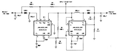
Dual Tracking regulator circuit
Image
A IC MAX634 inverting regulator is combined with a IC MAX630 to provide a dual tracking approximately 15 Volt output from a 12 Volt DC battery. The reference for the - 15 Volt output is derived from the positive output via R3 and R4. Both regulators are set to maximize output power at low battery voltages by reducing the oscillator frequency , via LBR, when V Batt falls to 8,5 volt. Technical instruction : Max. Input voltage    : 13 Volt / N/a mA Max. Output voltage :-15 Volt , + 15 volt / 45 mA

FM Tracking transmitter

Image
Description. T he circuit presented her will transmit a audio tone in the FM  band. The circuit can be used as a tracking signal transmitter or a remote control transmitter. The circuit uses only easily available components and any one can build this. The transmitter has a range of 100m @ 9V supply, with a matching antenna. The NE555 timer (IC1) is used for producing the audio tone. The first JFET (Q1) is wired as a Hartley oscillator which is frequency modulated by the audio tone. The second (Q2) JFET is wired as a buffer to isolate the oscillator based on Q1 from the antenna. The diode D1 is used as a varactor here. The diode is reverse biased by the ramping voltage produced at the pin 6&2 of the IC1. This results in the change of junction capacitance of reverse biased diode, which in turn alters the frequency of the oscillator to attain the frequency modulation. Circuit diagram with Parts  list.  Notes.  The inductor L1 can be made by winding 5 turns of  ...