Posts

Showing posts with the label Test

How to Test a diode

Image
Hello Everyone ... Today i am going to show you how we test a diode using a digital multimeter.In this article, we will go over different tests that we can use to check whether a diode is good or not, all by utilizing the functions of a digital multimeter. There are many checks we can do to see if a diode is functioning the way it should. We will use and exploit the characteristics and behaviors that a diode should show if it is good and, in thus doing so, determine whether is good or defective.So let's start ... Test of a diode with the ohmmeter of a multimeter :   A very good test you can do is to check a diode with your multimeter set to the ohmmeter setting. This is a simple test we can do to check whether it is good, open, or shorted. So we take the ohmmeter and place it across the leads of the diode. The orientation is very important. Anode-Cathode Diode Resistance Test   We first take the ohmmeter and place the positive probe on the anode of the diode (the black part of...
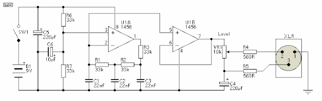
Microphone Circuit Test Oscillator Diagram

Image
Description This unit would be mounted in a small plastic or preferably metal box, with a 9V battery, level control, a male XLR connector (same as on a mic) and a switch.  Current drain is low, since the circuit only uses one dual opamp.  There is no need for a high quality device, and a 1458 is all that is needed. Circuit Diagram The first stage is the oscillator itself.  This is a simple three stage phase shift oscillator - a circuit that is remarkably uncommon - which is to say I have never seen it used elsewhere.  I designed it for another project a few years ago, and I don't understand why it is not more common. If you want to tune it, you can use a 50k pot instead of R1.  I suggest that if tuned, set it to A-440 Hz.  Frequency stability is not wonderful, and it changes by a few Hertz as the battery discharges, but this is unlikely to cause problems - it is a test oscillator, not a tuning standard.  As shown, frequency will be about 430Hz, dependi...

Test Multiteste LEDs Polarity Continuity Resistance Circuit

Image
What do you think of building a simple LED tester, so you can test the integrity of the components before soldering directly to the PCB. It reduces the task of testing the meter components using the circuit with LED gives an indication about the good or bad condition of the component. Test Multiteste LEDs - Polarity - Continuity - Resistance Circuit When a component is placed in the circuit and establishes electrical continuity T1 receives base current through R1. When T1 conducts, the green LED turns on and off the red LED. This indicates that the component to be tested is good. If the component is bad, will not have electrical continuity and T1 remains off. In this state only the red LED light indicating that the component is bad.   Polarity Connect the red end of the positive range to the circuit board and to test the black edge point. Circuit board under test to be lit Green LED ON - positive feed. Green LED off and red LED - or no negative supply voltage. Continuity Connect bo...