Chip Theremin Circuit Diagram
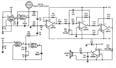
This schematic diagram show a single chip Theremin circuit. Theremin is an electronic music instrument which sense hand movement to control the tones/frequency. This Theremin circuit uses two separate Colpitts LC oscillators to produce a beat frequency. The frequencies of two Colpitts LC oscillators are mixed and then rectified. This rectification demodulate the mixed signal to get the beat frequency which is in audible range. This beat frequency or difference is the real Theremin’s output. The oscillator is operated at high frequency (inaudible) to get wide audible frequency range of beat frequency when two oscillator output is mixed. This circuit uses a 4011 quad gate to construct the high frequency oscillator operating at 250kHz. Here is the schematic diagram of the circuit. Single Chip Theremin Circuit Diagram The metal probe that is used to sense your hand produces only small frequency shift in term of percentage of original frequency...
