Posts

Showing posts with the label Sensor

Capacitive Sensor Circuit Schematic Diagram
Image
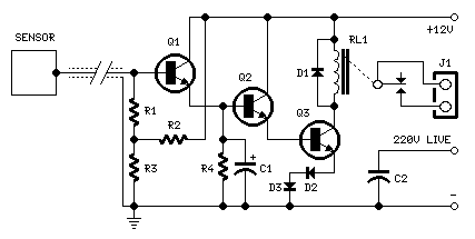
Special design for shop-windows animation Useful for many types of touch controls Circuit diagram: Parts: R1,R2_____1M 1/4W Resistors R3,R4____47K 1/4W Resistors C1_______10µF 25V Electrolytic Capacitor C2______470pF 630V Ceramic or Polyester Capacitor D1-D3____1N4002 100V 1A Diodes Q1-Q3_____BC337 45V 800mA NPN Transistors RL1_______Relay with SPDT 2A @ 220V switch Coil Voltage 12V. Coil resistance 200-300 Ohm J1________Two ways output socket Sensor____Aluminium or copper thin sheet with the dimensions of a post-card, glued at the rear of the same (about 15x10.5 cm.) Thin screened cable Circuit Description:  The purpose of this circuit is to animate shop-windows by means of a capacitive sensor placed behind a post-card-like banner. The card is placed against the glass inside the shop-window, and the visitor can activate the relay placing his hand on the card, from the outside. Especially suited for toy-shops, the circuit can activate model trains, small electric racing cars, lig...

Water Level Sensor Schematics

Image
This simple water level sensor circuit monitors the presence of water in a certain location or container. The circuit sends an acoustic alarm when it senses a drop of water leak. It is very simple to build and it is made of a single IC and some passive components. Check out the water level indicator circuit too! The IC LM1801 is a low power comparator that can deliver high output current if needed. When water hits the sensor, the reference voltage is overshot and the IC drives the ceramic transducer to beep. It is also possible to connect several sensors to the water level monitor circuit. The sensor can be easibly made out of a small piece of PCB that is etched with the proper pattern. The decoupling capacitor C3 is a 100uF/16V electrolytic capacitor.  source [link] 

Fog Lamp Sensor

Image
For several years now, a rear fog lamp has been mandatory for trailers and caravans in order to improve visibility under foggy conditions. When this fog lamp is switched on, the fog lamp of the pulling vehicle must be switched of to avoid irritating reflections. For this purpose, a mechanical switch is now built into the 13-way female connector in order to switch of the fog lamp of the pulling vehicle and switch on the fog lamp of the trailer or caravan. For anyone who uses a 7-way connector, this switching can also be implemented electronically with the aid of the circuit illustrated here. Fog Lamp Sensor Circuit Diagram:   Here a type P521 optocoupler detects whether the fog lamp of the caravan or trailer is connected. If the fog lamp is switched on in the car, a current flows through the caravan fog lamp via diodes D1 and D2. This causes the LED in the optocoupler to light up, with the result that the photo-transistor conducts and energies the relay via transistor T1. The relay ...

Parking sensor circuit

Image
Description The below circuit is a parking sensor circuit.This  circuit can be used as an aid for sensing the distance between the rear bumper of the car and any obstacle behind the car. The distance can be understood from the combination of the LEDs (D5 to D7) glowing. At 25cm D7 will glow, at 20 cm D7&D6 will glow and at 5cm D7, D6 and D5 will glow. When the obstacle is beyond 25 cm none of the above LEDs will glow. Two ICs are used in the circuit. The IC1 (NE555) is wired as an astable multivibrator for driving the IR Diode D1 to emit IR pulses. The operating frequency of the transmitter is set to be 120Hz.The IR pulses transmitted by D1 will be reflected by the obstacle and received by the D2 (IR photo diode).The received signal will be amplified by IC2a.The peak of the amplified signal will be detected by the diode D4 and capacitor C4.R5 and R6 compensates the forward voltage drop of D4.The output voltage of the peak detector will be proportional to the distance between ca...