Posts

Showing posts from January, 2017

Your PC Needs Some Illumination

Image
Try to lighten up you PC by using LED flex lights to surround the casing. The result will be much appreciated when the room is dark. The chain is housed in rubber plastic which makes more light to be projected out right angles as if some miracle is happening inside the PC. You can choose which color to use or what you wish to blend with the design of your room. The LED strips are very flexible and customizable which makes them popular. It is very easy to install these strips by using Velcro strips of adhesive backing. You may also use the LED strips in any part of your room like the hairdresser mirror. Click here to visit the project page.

Loading coil antena telex 88 108mhz

Image
This post is for an antenna loading coil telex broadcast on freq. let us buy Simply put wrote specifically for the antenna loading coil at the store component telex, because loading the settings is still for freq 2 meter, we must slightly modify it. The trick is easy, just replace the existing loops. original about 5 convolution convolution continues we replace 10 with 1 to 1.5 mm diameter wire. for more details see the pictures. may be useful ..

High HiFi Power Amplifier with MOSFET

Image
Circuit amplifier "High Power HiFi Power Amplifier With MOSFET" is capable of giving the output power to the load speakers 240Watt and 380Watt 8Ohm to load 4Ohm speakers. Voltage source to a series of power amplifiers "High Power HiFi Power Amplifier With MOSFET" This is a CT 25V 50V 25V to 50V CT of transformer CT. In making this power amplifier needs to be installed heatsinks on the power amplifier (MOSFET) in order to avoid excessive heat. The series of power supply to power amplifer can use the transformer 5A-20A and 35A mounted diode bridge and capacitors for a minimum of 2x 10.000uF electrolit. Details for the power amplifier circuit can be seen in the following figure. High Power Series HiFi Power Amplifier With MOSFET can modify to increase power output by doubling the final power amplifier is based on the diiginkan. Power generated from doubling the final power amplifier will also double its power output of power amplifier circuit "High Power HiFi Powe

Infrared Remote Extender

Image
This project sprang from the need to be able to remotely control audio-visual equipment placed inside cupboards. RF-based commercial units such as those used for home theatre were found to be overkill for this application. The circuit is based on a commonly available infrared receiver module (IRX1) and a PIC12F675 microcontroller (IC1) – see circuit. Most infrared standards specify a nominal 38kHz carrier signal for data transmission, which the module receives and demodulates. Circuit diagram: Infrared Remote Extender Circuit Diagram Digital data output: The digital data output from the module is fed into GP2 (pin 5) of the PIC micro, where it’s received by the PIC program and duplicated on output GP1 (pin 6). This flashes the "Signal" LED to give a visual indication that the extender is receiving the remote control’s transmissions. Copyright: Silicon Chip Magazine

Simple Knight Rider lights Circuit for model cars

Image
This simple circuit drives 6 LEDs in 'Knight Rider scanner mode'. Power consumption depends mainly on the type of LEDs used if you use a 7555 (555 CMOS version). Simple Knight Rider lights Circuit Note That V DD and GND for the ICs are not shown in the circuit drawing. Pin-outs: (7)555 4017 1 GND 1 Q5 9 Q8 2 TRIGGER 2 Q1 10 Q4 3 OUTPUT 3 Q0 11 Q9 4 RESET 4 Q2 12 CO 5 CONTROL VOLTAGE 5 Q6 13 NOT ENABLE 6 THRESHOLD 6 Q7 14 CLK 7 DISCHARGE 7 Q3 15 RESET 8 V DD 8 GND 16 V DD

ANIMAL CELL DIAGRAM

Image
Animal cell anatomy Animal Cell Diagram, Animal ... Saved from animal cell diagram ... Animal Cell Illustration With ... Plant and Animal Cell Diagrams ... animal cell diagram animal ... labeling plant animal cells ... Labeled Animal Cell Diagram Click on the picture to be ...

Fire alarm with light sensor

Image
Fire alarm can be made with a light sensor (LDR) as in the article with the title of Fire Alarm with this LDR sensor. Principles of fire detection Fire Alarm with LDR sensor is to detect the presence of smoke through the LDR. LDR in the series Fire Alarm does not stand alone in detecting a fire, but the LDR in the pair with the light shining on the LDR. Hence, in the detected smoke from the fire then the intensity of light received by the LDR LDR decreases and eventually trigger an alarm system on a series of Fire Alarm with this LDR sensor. Part 2 that in the series of Fire Alarm with Sensor LDR are some of the sensors, tone generator, audio power. Image Series Fire Alarm with Sensor LDR Function Section of the Fire Alarm with Sensor LDR Part of LDR and light sensor facing to fire smoke detection Part trigger using transistors and regulators as a trigger tone generator 7805 Tone generator section with IC UM66 Power audio section uses an audio power IC TDA 2002 which is equipped with v

Under the stairs

Image
I’m really behind on the updates, sorry. I’ve been doing some real-world stuff that didn’t leave much time for much DIY guitar-related fun. I am happy to report that one of the reasons I haven’t had as much time to tinker is that I’ve actually been playing the guitar a bit. One of the things that took up some of my time was sorting out a new property back home, which required a rather long return flight, not helped by the fact that the airline forgot to load the headphones for the entertainment system on the way there, and I hadn’t brought my own for the first time ever. While I was back home, I rifled through some stuff that I had left at a friend’s house and stumbled across a stomp box I made just after finishing the DIY Strat. I had totally forgotten about it, and even if I had remembered I would have been sure it had been thrown out. Anyway, for the very few that may be interested, here it is. Note the professional enclosure (not)! What a great colour (grey primer covered by lacque

Battery Charging Indicator For Mains Adaptor

Image
Although you may well be the proud owner of the very latest NiCd battery charger, you may still come across the odd 'incompatible' battery, for example, one having a rare voltage or requiring a much higher charging current than can be supplied by your off-the-shelf charger. In these cases, many of you will resort to an adjustable mains adaptor (say, a 500-mA type) because that is probably the cheapest way of providing the direct voltage required to charge the battery. Not fast and not very efficient, this 'rustic' charging system works, although subject to the following restrictions: Circuit diagram: Battery-Charging Indicator Circuit Diagram You should have some idea of the charging current. In case you use an adaptor which is adjustable but of the unregulated, low output current type, you can adjust the current by adjusting the output voltage. You have to know if the current actually flows through the battery. A current-detecting indicator is therefore much t

RGB Lights Circuit Diagram

Image
The overall effect produced by this project is a glowing sequence of lights changing slowly from one colour to the next. The microcontroller cycles through randomly generated values of red, green and blue hues of light to produce a variety of nice colours. The software implemented on the controller interpolates from one shade to another, each colour channel being treated independently. Light intensity is controlled by means of pulse width modulation (PWM) for each colour. A high frequency of approximately 60 Hz is used to modify the light intensity and eliminate any flicker that might arise. RGB Lights Circuit Diagram One major problem that had to be over-come was unequal brightness of the LEDs used, the result of which is a tendency for one particular colour to dominate in the overall hue produced. It was found that blue LEDs are perceived to have the largest intensity and green, the lowest. This was compensated for by using a large resistor for blue and a low resistor for green, tog

Purported press image of iPhone 5C appears online

Image
While the purported iPhone 5C, Apple's low-cost iPhone, has made several online appearances, including in some really high resolution pictures and videos that surfaced on the Internet, a website now claims to have published the official press shots of the phone. Romania based publication, Mobilissimo.ro, claims that a Romanian retailer sent a couple of press shots of the iPhone 5C to the website. The press photo features the White coloured variant of the iPhone 5C running iOS 7.The front panel is also in White unlike some previous leaks, while the back of the phone features the same plastic polycarbonate body panel that appeared in recent leaks, in glossy White, complete with a round camera lens and LED flash, Apple logo and iPhone branding. The left-hand side of the phone features the same pill shaped volume rocker and mute keys that had appeared online, in a recent leak. These are also White in colour. In addition to the press pictures, the site has also posted images of what the

Basic Functionality

A functional requirement usually has corresponding behavioral and performance condition Functional requirements can always be modelled

Electronic Digital Combination lock Circuit Diagram

Image
The circuit above above makes use of the CMOS 4017 decade counter IC. Each depression of a switch steps the output through 0– 9. By coupling the output via an AND gate to the next IC, a predefined code has to be input to create the output. Each PBS switch is de bounced by tw1o gates of a CMOS4001 quad 2-input NOR gate. This ensures a clean pulse to the input of each CMOS4017 counter. Only when the correct number of presses at PBS Awill allow PBS B to become active. This is similar for PBS C and PBS D. At IC4, PBS D must be pressed 7 times. Then PBS C is again pressed 7 times, stepping from output 1 to output 8. The AND gate formed around CMOS4081 then goes high, lighting the LED. The Reset switch can be pressed at any time. Power on resetis provided by the 100n capacitor near the reset switch. Below is a picture of one that I made about 15 years ago:   Unfortunately, this board was part of a much larger project containing multiple power supplies. One day whilst working on another circu

Simple Baud Rate Generator Circuit Project

Image
 This is a Simple Baud Rate Generator Circuit Project. In this article, an RC oscillator is used as a baud rate generator. If you can calibrate the frequency of such a circuit sufficiently accurately (within a few percent) using a frequency meter, it will work very well. However, it may well drift a bit after some time, and then…. Consequently, here we present a small crystal-controlled oscillator. If you start with a crystal frequency of 2.45765 MHz and divide it by multiples of 2, you can very nicely obtain the well-known baud rates of 9600, 4800, 2400, 600, 300, 150 and 75. If you look closely at this series, you will see that 1200 baud is missing, since divider in the 4060 has no Q10 output!  Baud Rate Generator Circuit Diagram If you do not need 1200 baud, this is not a problem. However, seeing that 1200 baud is used in practice more often than 600 baud, we have put a divide-by-two stage in the circuit after the 4060, in the form of a 74HC74 flip-flop. This yields a similar series

Thinking outside the planar

Image
The IMAGE spacecraft was launched from Vandenberg AFB in 2000 to study the aurora borealis or “Northern Lights”. IMAGE was the first satellite mission dedicated to imaging the Earth’s magnetosphere, the region of space controlled by the Earth’s magnetic field and containing extremely tenuous plasmas of both solar and terrestrial origin. IMAGE is an acronym for Imager for Magnetopause-to-Aurora Global Exploration. This is the high voltage power converter module for the Far-Ultraviolet (FUV) imaging instrument in the IMAGE satellite. It converts 28V to 5000V DC for the Wideband Imaging Camera (WIC). The WIC images the whole Earth and the auroral oval from satellite distances greater than 4 Earth radii to the center of the Earth. It selects the spectral range between 140 nm and 160 nm in the ultraviolet part of the optical spectrum. Here is a good intro video on the science, and subsequent satellite missions: “What triggers the sudden, magnificent movements of the aurorae that appear arou

800W Power Amplifier MOSFET

Image
This Figure is a schematic power amplifier with power 800 Watt and driver and booster using MOSFET. Audio Power Amplifier with power output 800W

RS232 to RS485 Circuit

Image
The new archetypal of RS485 advocate overcomes the RTS controlled botheration accomplished by our chargeless design. However, to do that requires a microprocessor, so there is a greater complication to the design. We advertise this unit, although currently we are attached our sales to barter who can pay by coffer alteration – which in absoluteness is bounded Australian companies.  This architecture has been almost agitation free, and if you crave quantities we can acclimate the adapter pinout to clothing your appliance – about again the accessory will no best fit the simple little D25 case in which you see it pictured. Click image to view larger RS232 to RS485 Circuit * Data (vs RTS) controlled – does not rely on PC handshake timing * DB25 RS232 connector compatible with PC * TxD and RxD translated from RS232 to RS485 * Direction of transmission controlled by Data * Handshake loop the PC connection so it works with all software * RS485 signals output on D9 male with lots of Ground pins

Gibson Deluxe Tuners part three the fix

Image
Please note that this post is part three of four posts. I highly recommend reading all four posts in order before acting on any of the information. The other parts are located here: Part 1: http://diystrat.blogspot.com/2009/01/gibson-deluxe-tuners-and-why-they-suck.html Part 2: http://diystrat.blogspot.com/2009/01/gibson-deluxe-tuners-part-two.html Part 4: http://diystrat.blogspot.com/2010/01/gibson-deluxe-tuners-revisit.html OK! Done! I tried various different options and finally settled on one that I was very happy with. Ironically, it was the one I thought wouldn’t work – the solder fix. I had already tried the glue repair in the past, but it eventually broke again, so I didn’t even bother trying this time. However, it was going to be my last-resort fix if necessary. Before I show you the solder fix, I should mention that I did try the metal strap solution first. I cut out a little paper template to fit over the tuner and then went hunting for a suitable piece of metal. (paper templ

Inverter 12V to 220V 100W by Transistor

Image
This circuit is 100 watt power inverter using power transistor 2N3055 . It is designed for you that need to use appliances at outdoor or no electrical places. Someone use it in car or the high mountain etc. The maximum output power of this circuit about 100 watts, it is suitable for a normal lighting (all home lamps), also used for radio, mini TV, stereo or someone use it for   How it works   From the schematic diagram in Figure 1 this circuit will include of 4 main section are: 1. The transistors Q1,Q2 act as the frequency oscillator circuit. 2. Both transistors Q3,Q4 act as the frequency divider circuit 3. The Q5,Q6 act as the driver circuit. 4. The Q7,Q8 act as the output circuit. Let’s look at to both transistors Q1,Q2 will be connected together as the astable multivibrator form. It will generate the output frequency about 100 Hz at the collector lead of Q2. Then this signal will sent to the two frequency divider makes the frequency is reduced down about 50Hz Cause we don

Simple Medium Wave Modulator

Image
If you insist on using a valve radio and listening to medium-wave stations, you have a problem: the existing broadcasters have only a limited number of records. Here there’s only one remedy, which is to build your own medium-wave transmitter. After that, you can play your own CDs via the radio. The transmitter frequency is stabilised using a 976-kHz ceramic resonator taken from a TV remote control unit. Fine tuning is provided by the trimmer capacitor. If there’s another station in the background, which will probably be weak, you can tune it to a heterodyne null, such as 981 kHz. As an operator of a medium-wave transmitter, that’s your obligation with respect to the frequency allocations. And that’s despite the fact that the range of the transmitter is quite modest. The small ferrite coil in the transmitter couples directly into the ferrite rod antenna in the radio. Medium-Wave Modulator Circuit Diagram The modulator is designed as an emitter follower that modulates the supply voltage

DOD Wah Filter DOD 545

Image

Active Short Wave Antenna

Image
The circuit presented here illustrates the fact that in spite of all kinds of new component and technology, it is still possible to design useful, and interesting, circuits. The circuit is based on two well-established transistors, a Type BF256C and a BF494. In conjunction with the requisite resistors and capacitors, these form a well-working antenna amplifier. Note that they are direct coupled. Transistor T1 is the input amplifier cum buffer, while the BF494, in a common-ground configuration, provides the necessary amplification. The amplifier is designed for operation at frequencies between 10 MHz and 30 MHz, which is the larger part of the short-wave range, and has a gain of 20 dB. Inductor L1 is wound on an Amidon core Type T-37-6. The primary consists of 2 turns, and the secondary of 12 turns 0.3 mm dia. enameled copper wire. The number of turns may be experimented with for other frequency ranges. The input circuit is tuned to the wanted station with capacitor C1. The response of

A Simple Hearing Aid

Image
Commercially available hearing aids are quite costly. Here is an inexpensive hearing aid circuit that uses just four transistors and a few passive components. Hearing Aid Circuit Diagram Parts: R1 = 2.2K R2 = 680K R3 = 3.3k R4 = 220K R5 = 1.5K R6 = 220R R7 = 100K R8 = 680K C1 = 104pF C2 = 104pF C3 = 1uF/10V C4 = 100uF/10V C5 = 100uF/10V Q1 = BC549 Q2 = BC548 Q3 = BC548 Q4 = BC558 J1 = Headphone jack B1 = 2x1.5V Cells SW1 = On/Off-Switch Circuit Operation: On moving power switch SW1 to ‘on’ position, the condenser microphone detects the sound signal, which is amplified by Q1 and Q2. Now the amplified signal passes through coupling capacitor C3 to the base of Q3. The signal is further amplified by Q4 to drive a low impedance earphone. Capacitors C4 and C5 are the power supply decoupling capacitors. The circuit can be easily assembled on a small, general-purpose PCB or a Vero board. It operates off a 3V DC supply. For this, you may use two small 1.5V cells. Keep switch S to ‘off’ state wh

Direction Sensor CMPS03

Image
CMPS03 Compass Module Overview Compass is a tool for navigation for a direction, a direction in this article referred to is the magnetic module CMPS03 Compas. Magnetic Compass Module CMPS03 often used in making robots in the contest. Magnetic Compass Module Functions in the contest  CMPS03 usually to provide a reference where the robots are in position and lead anywhere, then the position and direction provided by the Magnetic Compass Module reference sebgai CMPS03 the next robot motion. Magnetic Compass Module uses I2C data communication lines to mirokontroler. With adalanya I2C data communication lines from this CMPS03 this module can be connected directly to a microcontroller that suport with I2C data communication channels such as AVR ATMega. Magnetic Compass Module CMPS03 require 5 V voltage with 15mA current. CMPS03 Circuit Diagram Because the module using I2C Magnetic Compass CMPS03 we can use 5 lines are: VCC + 5 V on pin 1 SCL with Pull Up resistor 10 K SDA with Pull Up resist

Cheap and Simple Gate Alarm Circuit Diagram

Image
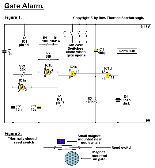
This is the Cheap and Simple Gate Alarm Circuit Diagram. A cheap and simple gate alarm made from a single CMOS Integrated Circuit.  Cheap and Simple Gate Alarm Circuit Diagram Circuit Notes Figure 1 represents a cheap and simple Gate Alarm, that is intended to run off a small universal AC-DC power supply. IC1a is a fast oscillator, and IC1b a slow oscillator, which are combined through IC1c to emit a high pip-pip-pip warning sound when a gate (or window, etc.) is opened. The circuit is intended not so much to sound like a siren or warning device, but rather to give the impression: "You have been noticed." R1 and D1 may be omitted, and the value of R2 perhaps reduced, to make the Gate Alarm sound more like a warning device. VR1 adjusts the frequency of the sound emitted. IC1d is a timer which causes the Gate Alarm to emit some 20 to 30 further pips after the gate has been closed again, before it falls silent, as if to say: "I'm more clever than a simple on-off device.

Multimedia RIAA Preamplifier Circuit Diagram

Image
Even if a large number of album titles once available on vinyl are now, little by little, being proposed as CDs, not all are available and far from it. You may have treasures in your collection that you would like to burn on CDs. First, preserving a CD is easier than preserving a vinyl record, and second, we have to admit that turntables are disappearing, even on fully-equipped Hi-Fi systems. From a point of view of software and PCs, converting from vinyl to CD is not a problem. A large number of programs, whether paid for freeware, are available to re-master vinyl records with varying degrees of success and to eliminate pops, crackles and other undesirable noises. All of these programs work with the sound card of your PC and that, admittedly, is where the problem starts. Most high-quality turntables are equipped with a magnetic cartridge which typically delivers just a few mV. The cartridge signal requires a correction of a specific frequency, called RIAA correction. If our older read

2 3 Watt Low audio power amplifier

Image
These amplifiers using IC KA2202 and KA2207, which has a power output of 2.3 Watt berimpedansi 4 ohms. Minimum supply voltage and maximum 5Volt 20Volt. See schematics and component list below. Part List  R1 = 100K R2 = 56R R3 = 56R R4 = 1R Use 1/4 Watt resistor C1 = 100uF C2 = 100uF C4 = 100uF C5 = 470uF C6 = 100nF C7 = 470pF C8 = 2,2nF C9 = 100uF U1 = KA2202 , KA2207

Simple Electronic Lock

Image
There are six (or more) push switches. To 'unlock' you must press all the correct ones at the same time, but not press any of the cancel switches. Pressing just one cancel switch will prevent the circuit unlocking. When the circuit unlocks it actually just turns on an LED for about one second, but it is intended to be adapted to turn on a relay which could be used to switch on another circuit. Please Note: This circuit just turns on an LED for about one second when the correct switches are pressed. It does not actually lock or unlock anything! Simple Electronic Lock Circuit diagram :   Simple Electronic Lock Circuit Diagram Stripboard Layout : Parts : resistors: 470, 100k ×2, 1M capacitors: 0.1μF, 1μF 16V radial on/off switch push-switch ×6 (or more) stripboard 12 rows × 25 holes red LED 555 timer IC 8-pin DIL socket for IC battery clip for 9V PP3   A kit for this project is available from RSH Electronics: www.kpsec.freeuk.com Copyright :John Hewes 2006,  The Electronics Club

Tuned Radio Frequency TRF Receiver Circuit Project

Image
This is a simple project of Tuned Radio Frequency (TRF) Receiver Circuit diagram. Super heterodyne receivers have been mass-produced since around 1924, but for reasons of cost did not become successful until the 1930s. Before the second world war other, simpler receiver technologies such as the TRF receiver and the regenerative receiver were still widespread. Tuned Radio Frequency (TRF) Receiver Circuit diagram :   Tuned Radio Frequency (TRF) Receiver Circuit Diagram The circuit described here is based on the old technology, but brought up-to-date a The most important part of the circuit is the input stage, where positive feedback is used to achieve good sensitivity and selectivity. The first stage is adjusted so that it is not quite at the point of oscillation. This increases the gain and the selectivity, giving a narrow bandwidth. To achieve this, the potentiometer connected to the drain of the FET must be adjusted very carefully: optimal performance of the receiver depends on its

Simple Refrigerator Door Alarm Circuit Diagram

Image
This is the simple Simple Refrigerator Door Alarm Circuit Diagram. Does your celery reach out to keep the door from closing properly when you turn your back? Here's a simple circuit that beeps whenever the door is open for an extended period of time (which will also put a little pressure on the fridge loiterers in the house). Simple Refrigerator Door Alarm Circuit Diagram The photocell has a very high resistance in the dark which drops very low when the door opens and the light turns on. The 22 uF capacitor begins to charge and when the voltage reaches the zener voltage, the beeper sounds. Closing the door allows the capacitor to discharge through the 10 meg.  resistor, resetting the beeper. The circuit draws very little power when the door is shut and only draws significant current when the beeper is sounding. The transistor may be a single NPN darlington such as the MPS-A14 or two 2N4401's connected as shown. Other types will also work. The delay may be changed by changing th

Game Show Indicator Lights Whos First

Image
The circuit below turns on a light corresponding to the first of several buttons pressed in a "Who's First" game. Three stages are shown but the circuit can be extended to include any number of buttons and lamps. Game Show Indicator Lights Circuit Diagram: Three SCRs (silicon controlled rectifiers) are connected with a common cathode resistor (50 ohm) so that when any SCR conducts, the voltage on the cathodes will rise about 7 volts above the voltage at the junction of the 51K and 1K ohm resistors and prevent triggering of a second SCR. When all lamps are off, and a button is pressed, the corresponding SCR is triggered due to the voltage at the divider junction being higher than the cathode. Once triggered, the SCR will remain conducting until current is interrupted by the reset switch. Or, you can just turn the power off and back on. A 50 ohm, 5 watt resistor was selected to produce a 10 volt drop at 200 mA when a single 25 watt lamp comes on. Higher wattage lamps would

Cheap Bicycle Alarm Schematics Circuit Diagram

Image
The author wanted a very cheap and simple alarm for some of his possessions, such as his electrically assisted bicycle. This alarm is based on a cheap window alarm, which has a time-switch added to it with a 1-minute time-out. The output  pulse of the 555 replaces the reed switch in the window alarm. The 555 is triggered by a sensor mounted near the front  wheel, in combination with a magnet that is mounted on the spokes. This sensor and the magnet were taken from a cheap bicycle computer.  Circuit diagram : Cheap Bicycle Alarm Circuit Diagram The front wheel of the bicycle is kept unlocked, so that the reed  switch closes momentarily when the wheel turns. This  triggers the 555, which in turn activates the window alarm. The circuit around the 555 takes very little current and can  be powered by the batteries in the window alarm.  There  is just enough room  left inside the enclosure of the window  alarm to mount the time-switch inside it.  The result is a very cheap, compact device,

Power 2h 30 Vatt 12 volts working scheme

Image
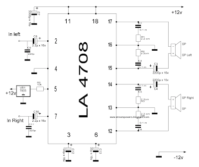
Not expensive, High-quality sound, Small parts and easy to assemble, Do not need to be tuned.Today can offer to your attention an amplifier that I have gathered from (almost) stuff I have lying in store. Long ago, working in the workshop, we often filmed amplifiers machines, since they come without tape recorders ​​and to put an ordinary tape recorder had to dismantle the amplifiers are !!! I left a couple of times since amplifier chips such as the LA4708. Time has passed since then a lot until my sister had not asked to do anything for his laptop to play in the yard with an acceptable quality and loud sound as speakers 2 pcs idle at home! Power 2h-30-Vatt 12 volts, working scheme It is taken from the datasheet half and half just from the people and schemes are proven over the years !!! If you look at the diagram, the capacitors C3 and C4 - a savings standing on the output of the amplifier, without a way (as if the sound disappears at high bass and not enough to drive the speakers). Th