Posts

Showing posts with the label FM

Simple 1 Watt PLL FM Broadcast Transmitter

Image
To day i share a little power for my friends.This is a Simple 1 Watt PLL FM Broadcast Transmitter . The RF output varies from 500mW to about 1.2W depending on the frequency selected and RF output transistor used. Motorola 2N4427 always seems to work well. Transmitter uses CMOS PLL VCO that prevents the frequency drifts. The frequency is selected via DIP switches. The transmitter is supplied by 12V DC and can also be powered from the battery.   Simple 1 Watt PLL FM Broadcast Transmitter

Build a 9V Wireless Microphone FM Transmitter

Image
This FM transmitter circuit can be used as a wireless microphone,  can be received by an ordinary 88- to 108-MHz FM broadcast receiver. For the power supply, this transmitter circuit is powered by a 9 V battery. To comply with the radiation limit of FCC rules, keep the antenna length under 12 inches. L1 is 6 turns of #24 wire wound around a pencil or a 1/4″ form, with turns spacing of 1 wire diameter. C6 is a gimmick capacitor which has value about 1 pF.  9V Wireless Microphone FM Transmitter Circuit Diagram

Simple 3 Volts FM Transmitter Schematic

Image
This is a simple and useful circuit diagram of an FM transmitter is sown in this schematic . This FM Transmitter software is very simple and it has a acceptable transmission . The signal transited from this FM transmitter can be received at almost 300 meters in open air The circuit require a 3volts operating voltage and can be tuned anywhere in the FM band. 3V FM Transmitter Circuit Diagram You can use this emitter circuit to transmit signal from your house to garden or from room to room . To listen the signal you can use any radio (portable or not ) that can work on FM band . Connect a half or quarter wavelength antenna (length of wire) to the aerial point. At an FM frequency of 100 MHz these lengths are 150 cm and 75 cm respectively. The calibration of this FM emitter circuit is very simple and you need just to place a radio at some distance from the transmitter and set it somewhere about 88-107MHZ( chose the transmission frequency ) and after that vary the transmitter oscillator fre...

Simple FM stereo decoder circuit using MC1310P IC

Image
Simple FM stereo decoder circuit using MC1310P IC via next.gr

FM Moulator with IC 555

Image
FM Modulator circuit is a simple FM modulation circuit using IC 555, where the resulting modulated signal has a tenuous meeting depends on the signal frequency information.  The resulting signal can be spelled out quite nice and stable so that the result will be more perfect. No winding or inductor in series modulator, so you do not need to bother to make a winding and calculate the value of the coil that you created it. With this circuit the desired value of frequency modulation can be obtained easily by calculating the frequency of IC 555 in general, which is determined by the resistor 6.8 K and 3.3 K and 0.1 UF capacitor. To obtain the other frequencies of your stay replace one or all three components. Actually fm modulator ic 555 circuit is very simple though, but I think it reliable enough to handle a simple application purposes that do not require a big power or a very high frequency. But if you want more power you can add the RF amplifier circuit at the output of this circui...

FM Transmitter Circuit with OPamp

Image
FM Transmitter Circuit with OPamp Parts List: R1 4K7 R4 150K R7 3K9 (2K7) R2 4K7 R5 220R R8 120R (82R) R3 4K7 R6 4K7 All resistors except R8 are at least 0.25W rated. R8 is at least 0.5W rated (the 0.6W metal film M-series from Maplin can be used for R1-R8). C1 1n C4 22uF C7 10n C10 1n C2 4u7 C5 1n C8 1n C3 1n C6 10n C9 33pF VC1 5-60pF IC1 LM358 Q1 ZTX108 Notes: L1 is 0.112uH (this tunes to the middle of the FM band, 98 MHz, with VC1 at its centre value of 33pF). L1 is 5 turns of 22 swg enamelled copper wire close-wound on a 5mm (3/16") diameter former. Alternatively, you can have a fixed 33pF cap instead of VC1 and have L1 as an adjustable molded coil (eg UF64U from Maplin). VC1 will give you a tuning range of 85 - 125 MHz, and a possible choice is the Philips type polypropylene film trimmer (Maplin code WL72P). Two sets of oscillator bias resistors are given, the ones in the brackets give about 20% more RF power. Mike is our favourite Omnidirectional sub-mini electret (Maplin c...

1 Watt PLL FM Broadcast Transmitter Circuit

Image
To day i share a little power for my friends.This is a Simple 1 Watt PLL FM Broadcast Transmitter. The RF output varies from 500mW to about 1.2W depending on the frequency selected and RF output transistor used. Motorola 2N4427 always seems to work well. Transmitter uses CMOS PLL VCO that prevents the frequency drifts. The frequency is selected via DIP switches. The transmitter is supplied by 12V DC and can also be powered from the battery.   Simple 1 Watt PLL FM Broadcast Transmitter

TDA7338 FM stereo decoder circuit design

Image
The pilot detector output is designed as an open collector output, therefore an external pull up resistor is needed. To force the decoder to `MONO` Pin 19 has to be clamped to a voltage below 0. 8V. visit page. TDA7338 FM stereo decoder circuit design

Four Stage FM Transmitter

Image
This FM transmitter circuit uses four radio frequency stages: a VHF oscillator built around transistor BF494 (T1), a preamplifier built around transistor BF200 (T2), a driver built around transistor 2N2219 (T3) and a power amplifier built around transistor 2N3866 (T4). A condenser microphone is connected at the input of the oscillator. Circuits diagram : Four-Stage FM Transmitter Circuits Diagram Working of the circuit is simple. When you speak near the microphone, frequency-modulated signals are obtained at the collector of oscillator transistor T1. The FM signals are amplified by the VHF preamplifier and the pre-driver stage. You can also use transistor 2N5109 in place of 2N2219. The preamplifier is a tuned class-A RF amplifier and the driver is a class-C amplifier. Signals are finally fed to the class-C RF power amplifier, which delivers RF power to a 50-ohm horizontal dipole or ground plane antenna. Use a heat-sink with transistor 2N3866 for heat dissipation. Carefully adjust ...

Digital AM FM signal Processor

Image
General Description: The TDA7500 is an integrated circuit implementing a fully digital, integrated and advanced solution to perform the signal processing in front of the power amplifier and behind the AM/FM tuner or any other audio sources. The chip integrates two 43 MIPs DSP cores: one for stereo decoding noise blanking, weak signal processing and multipach detection and one for sound processing. Block Diagram:  

Acetone Fuzz Master FM 1

Image

FM Transmitter Bug

Image
Circuit diagram Notes: This small transmitter uses a hartley type oscillator. Normally the capacitor in the tank circuit would connect at the base of the transistor, but at VHF the base emitter capacitance of the transistor acts as a short circuit, so in effect, it still is. The coil is four turns of 18swg wire wound around a quarter inch former. The aerial tap is about one and a half turns from the supply end. Audio sensitivity is very good when used with an ECM type microphone insert

Simple VHF FM Aircraft Receiver

Image
VHF FM Aircraft Receiver is a supererogation receiver developed for listening to FM transmitters but also tunes the aircraft band and the top portion of the FM broadcast band. Receives both AM and FM (107mHz to 135 MHz). You can use this receiver with the any FM transmitter. The receiver is amazingly simple using only one transistor for the receiver section and one IC for the audio section. This circuit is a self-quenching regenerative RF receiver also known as a super regenerative receiver. A superregenerative receiver performs two basic functions.    First it feeds back a portion of the received signal from it’s output in phase to its input; and second a super audible quenching oscillator drives the amplifier through the point of oscillation and maximum sensitivity and then quenches the oscillation repeatedly. This keeps the feedback from driving the circuit into self-oscillation and allows the signal to be regenerated over and over again. In this version of the circuit, ...

FM Booster Diagram Circuit

Image
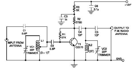
Description A low-cost circuit of an FM booster that can be used to listen programs from distant FM stations clearly. The circuit comprises a common-emitter tuned RF preamplifier wired around VHF/UHF transistor 2SC2570 ( C2570). This FM booster circuit is constructed using few common components ( not require some special components ) and provide a very good gain . To calibrate this circuit you need to adjust input/output trimmers (VC1/VC2) for maximum gain. Input coil L1 consists of four turns of 20SWG enamelled copper wire (slightly space wound) over 5mm diameter former. It is tapped at the first turn from ground lead side. Coil L2 is similar to L1, but has only three turns. Both of the trimmers are 22pF value .This FM radio signal booster needs to be powered by a 12 volts DC power supply . Circuit Diagram Source - http://www.electroniq.net/radio-frequency/fm-booster-schematic-circuit.html

House fm transmitter 88 108MHz at 4 Watt

Image
This is Fm transmitter circuit for house. It is modulation type Mono FM and Frequency range 88-108 MHz. By it have Working voltage range 12-18 VDC and use current max at 450mA only. This circuit convenient for , because , have good small-sized. It is the ideal project for the beginner who wishes to get started in the fascinating world of FM broadcasting and wants a good basic circuit. This circuit use the transistor the important , be the number is 2N3553.

FM Tracking transmitter

Image
Description. T he circuit presented her will transmit a audio tone in the FM  band. The circuit can be used as a tracking signal transmitter or a remote control transmitter. The circuit uses only easily available components and any one can build this. The transmitter has a range of 100m @ 9V supply, with a matching antenna. The NE555 timer (IC1) is used for producing the audio tone. The first JFET (Q1) is wired as a Hartley oscillator which is frequency modulated by the audio tone. The second (Q2) JFET is wired as a buffer to isolate the oscillator based on Q1 from the antenna. The diode D1 is used as a varactor here. The diode is reverse biased by the ramping voltage produced at the pin 6&2 of the IC1. This results in the change of junction capacitance of reverse biased diode, which in turn alters the frequency of the oscillator to attain the frequency modulation. Circuit diagram with Parts  list.  Notes.  The inductor L1 can be made by winding 5 turns of  ...

3W FM Transmitter

Image
      This is the schematic for an FM transmitter with 3 to 3.5 W output power that can be used between 90 and 110 MHz. Although the stability isn't so bad, a PLL can be used on this circuit. This is a circuit that I've build a few years ago for a friend, who used it in combination with the BLY88 amplifier to obtain 20 W output power. From the notes that I made at the original schematic, it worked fine with a SWR of 1 : 1.05 (quite normal at my place with my antenna). Circuit diagram   Parts: R1,R4,R14,R15 10K 1/4W Resistor R2,R3 22K 1/4W Resistor R5,R13 3.9K 1/4W Resistor R6,R11 680 Ohm 1/4W Resistor R7 150 Ohm 1/4W Resistor R8,R12 100 Ohm 1/4W Resistor R9 68 Ohm 1/4W Resistor R10 6.8K 1/4W Resistor C1 4.7pF Ceramic Disc Capacitor C2,C3,C4,C5,C7,C11,C12 100nF Ceramic Disc Capacitor C6,C9,C10 10nF Ceramic Disc Capacitor C8,C14 60pF Trimmer Capacitor C13 82pF Ceramic Disc Capacitor C15 27pF Ceramic Disc Capacitor C16 22pF Ceramic Disc Capacitor C17 10uF 2...

9V FM Transmitter

Image
This fm transmitter circuit is a very simple and require few external components and operates in FM band above 100 MHz.This fm transmitter needs to be powered from a 9 volts battery or from another 9 volts regulated power supply .The tuned coil L1, has two output tapping for the antenna connection, marked "A" and "B". These are both low-level outputs and you choose which tapping you want to use ( stable low range, or more unstable but higher range). Tap B (2.5%) takes just a very small portion of signal from the oscillator circuit and therefore gives a very frequency stable transmitter. The output level (around 2.5mW) and range are therefore somewhat reduced.Tap A (10%) delivers very much more power (around 10mW) to the antenna load. This gives you a greater range, but at the expense of frequency stability.  9V FM Transmitter Circuit diagram All component leads should be kept as short as possible. The LINK wire on the PCB should lay flat on the PCB. Use the cutoff f...

Build a 4 Transistor FM Transmitter Circuit Diagram

Image
 4 Transistor FM Transmitter Circuit Diagram   Build a  4 Transistor FM Transmitter Circuit Diagram. This 4 Transistor FM Transmitter Circuit Diagram provides an FM modulated signal with an output power of around 500mW. The input microphone pre-amp is built around a couple of 2N3904 transistors (Q1/Q2), and audio gain is limited by the 5k preset trim potentiometer.  The oscillator is a colpitt stage, frequency of oscillation governed by the tank circuit made from two 5pF ceramic capacitors and the L2 inductor. The output stage operates as a 'Class D' amplifier, no direct bias is applied but the RF signal developed across the 3.9uH inductor is sufficient to drive this stage. The emitter resistor and 1k base resistor prevent instability and thermal runaway in this stage.

FM Wave Generation

Image
Frequency Modulation Another means of encoding a wave of information is by producing a complex wave whose frequency is varied in proportion to the instantaneous amplitude of the information wave. Such an encoding is frequency modulation. The result of this encoding or modulation process is a complex modulated wave whose instantaneous frequency is a function of the amplitude of the modulating wave and differs from the frequency of the carrier from instant to instant as the amplitude of the modulating wave varies. The following equation provides the equivalent formula for FM: v(t) Asin( t M sin( t)) c f i = w + w where, v(t) is the instantaneous voltage A is the peak value of the carrier wc is the carrier angular velocity Mf is the modulation index wi is the modulating signal angular velocity The FM formula is really complex. In figure 1 is the waveform of a FM signal. To solve for the frequency components of an FM wave requires the use of the Bessel functions. They show that frequency-m...