Posts

Showing posts with the label Dual

How to Make a Dual Tone Siren Circuit

Image
This electronic siren gives out a continuously varying high amplitude sound. Since the supply voltage is not critical, it can be used in cars, motor cycles or at home. It can replace the ordinary call bell. - . The circuit consists of two separate free running multivibrator and an oscillator. More innovative circuits HERE. A free running or astable multivibrator is one which has two quasi-stable states and the output of one stag is connected to the input of the other through a coupling capacitor.Since both the states are quasi-stable, the output attained is continuously varying in nature i.e. high, low high low-.  The output is in the form low pulses, the frequency of which depends on the base biasing resistor and the coupling capacitor, When these resistances and condensers for both the stages are of different values, the output ` wave form is rectangular; this is because the time constant of the two quasi-stable states becomes different. If this time constant of the two, states i...

Simple Dual Trace Scope Switch Circuit

Image
Simple Dual Trace Scope Switch Circuit Diagram. The switcher output goes to the single vertical input of the scope, and a sync line from one of the inputs is taken to the scope's external-sync input. Frequency response of the input amplifiers is 300 kHz over the range of the gain controls. With the gain controls wide open so no attenuation of the signal takes place, the frequency response is up to 1 MHz. Simple Dual Trace Scope Switch Circuit Diagram    

5 4W Dual Audio Power Amplifier

Image
General Description: The BA5415A and BA5416 are dual power amplifier ICs that operate off a 9V to 15V supply. When driving a 4Ω load off a 9V supply, the BA5415A does not require a heatsink. The BA5416 uses a lost-cost package. The basic characteristics (total harmonic distortion etc.) of the amplifiers are excellent, and both ICs include a standby switch function. Features High output. POUT = 5.4W (VCC = 12V, RL = 3Ω and THD = 10%) POUT = 2.5W (VCC = 9V, RL = 4Ω and THD = 10%) Excellent audio quality. THD = 0.1% (f = 1kHz, PO = 0.5W) VNO = 0.3mVrms (Rg = 10kΩ) RR = 60dB (fRR = 100Hz) Wide operating power supply voltage range. VCC = 5.0V to 18.0V (BA5416 : 5.0V to 15.0V) Switching noise (ìpopî noise) generated when the power is switched on and off is small. Ripple mixing when motor starts has been prevented. Built-in thermal shutout. Built-in standby switch. Output is not influenced by the standby pin voltage. Mute time does not depend on VCC. Soft clipping. Heatsink not required  ...

Dual High Side Switch Controller

Image
Circuit diagram : Dual High Side Switch Controller Circuit Diagram One of the most frequent uses of n-channel MOSFET’s is as a voltage controlled switch. To ensure that the MOSFET delivers the full supply voltage to the load it is necessary for the gate voltage to be a few volts above the supply voltage level. This can be a problem if no other suitable higher volt-age sources are available for use elsewhere in the circuit. The LTC 1982 dual high-side switch controller from Lin-ear Technology (www.linear-tech.com) solves this problem by incorporating a voltage tripler circuit in the gate driver stage. The gate voltage is limited to +7.5 V which is 2.0 V above the IC’s maximum operating voltage. It can directly drive the gate of logic-level MOSFET with a VGS(th) from 1.0 V to 2.0 V. A suitable n-channel logic level MOSFET would be the BSP 295. This device can switch up to 1.5 A and is available in an SOT 233 SMD package.

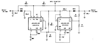
Dual Tracking regulator circuit

Image
A IC MAX634 inverting regulator is combined with a IC MAX630 to provide a dual tracking approximately 15 Volt output from a 12 Volt DC battery. The reference for the - 15 Volt output is derived from the positive output via R3 and R4. Both regulators are set to maximize output power at low battery voltages by reducing the oscillator frequency , via LBR, when V Batt falls to 8,5 volt. Technical instruction : Max. Input voltage    : 13 Volt / N/a mA Max. Output voltage :-15 Volt , + 15 volt / 45 mA

Dual Power Amplifier Using TDA7293 MOSFET IC

Image
As readers will know, there are already several power amplifier projects, two using IC power amps (aka power opamps). Both have been popular, and this project is not designed to replace either of them. However, it is significantly smaller than the others, so it makes building a multiple amp unit somewhat easier because the space demand is much lower. It's quite simple to include 4 amps (two boards) into a small space, but be aware that good heatsinking is essential if you expect to run these amps at significant power levels. Photo of Completed P127 Board The TDA7293 IC uses a MOSFET power stage, where the others featured use bipolar transistors. The main benefit of the MOSFET stage is that it doesn't need such radical protection circuitry as a bipolar stage, so unpleasant protection circuit artefacts are eliminated. There are no apparent downsides to the TDA7293, although it was found that one batch required a much higher voltage on the Standby and Mute pins than specified, or ...

Basic Dual Polarity Power Supply

Image
This is a very basic dual polarity power supply circuit diagram, it also called symmetrical power supply or split power supply. It just need the following components: A Center Tapped Transformer Diode rectifier 4 units (or diode bridge 1 unit) Electrolityc capacitor 4 units The value of each component are depending on your needs. For example, if you need dual polarity power supply to supply an 100W amplifier circuit which need 32V voltage supply, then the recommendation are as follow: Transformer: 3A center tapped transformer 24V – 0 – 24V. Diode rectifier 1N5402 : 4 units Electrolityc capacitor (elco) 4700uF/50V – 6800uF/50V : 4 units With above component’s value, the power supply will be able to handle 100W output load. Circuit note: Based on above scheme, the ground is connected to the “E” mark. The “E” is the center of the transformer. In center tap transformer, there are some outputs that have same values (24V for example) and an output which has 0 output. The ground (E) shou...

Dual Pre Amplifier for Car Radio

Image
Circuit diagram: Dual Pre-Amplifier for Car Radio Datasheet for AN7310: Download