Posts

Showing posts with the label COUNTER

Light Gate with Counter

Image
The circuit described here counts the number of times that an infrared beam is interrupted. It could be used to count the number of people entering a room, for instance, or how often a ball or another object passes through an opening (handy for playing shuffleboard). The heart of the circuit consists of you guessed it a light gate! Diode D1 is an IR diode that normally illuminates IR transistor T1. The light falling on T1 causes it to conduct to a certain extent. The resulting voltage on the collector of T1 should be just low enough to prevent the following transistor (T2) from conducting. This voltage can be adjusted within certain limits using P1.  Circuit diagram : Light Gate with Counter Circuit Diagram As soon as an object comes between D1 and T1, the light shining on T1 will be partially or fully blocked, causing the IR transistor to conduct less current. As a result, the voltage on its collector will increase, producing a brief rise in the voltage on the base of T2. This wi...

Infrared Object Counter Circuit Diagram

Image
This infrared object counter can be installed at the entry gate to count the total number of people entering any venue. For example, it can be used at the railway stations or bus stands to count the people arriving per day or week. The counter uses an infrared transmitter-receiver pair and a simple, low-cost calculator. It works even in the presence of normal light. The maximum detection range is about 10 metres. That means the transmitter and the receiver are to be installed (at the opposite pillars of the gate) not more than 10 metres apart. No focusing lens is required. If an 8-digit calculator is used the counter can count up to 99,999,999 easily, and if a 10-digit calculator is used the counter can count up to 9,999,999,999.  Fig. 1: Transmitter circuit Powered by a 9V battery, the transmitter circuit (see Fig. 1) comprises IC 555 (IC1), which is wired as an astable multivibrator with a centre frequency of about 38 kHz, and two infrared light-emitting diodes (LEDs). The receiv...

7 SEGMENT DISPLAY COUNTER INCOMING PERSON COUNTER

Image
Hiii…….friends today I am here with a very interesting projects for those who have just started with electronics. With this project we can display 0-9 digits on the 7 segment and we can count the no of persons entering in a room.  Circuit Diagram Here a counter IC 7490 is used along with BCD to 7 segment decoder IC 7447. The function of 7490 is to provide the counting value and decoder IC is decoding that value to 7 segment output . Every time when you will push the switch the clock of IC7490 will be triggered and as a result count will increase by 1 . Hence with this simple project we can display numbers 0 to 9 on seven segment display just by pressing switch. It’s a very easy circuit and you can easily implement it on a general purpose PCB . NOW ITS TIME TO MAKE USE OF THIS CIRCUIT IN COUNTING THE NUMBER OF PERSONS ENTERING IN THE ROOM...... LETS SEE HOW….?? So instead of using switch we will use LDR here , we will place LDR at the entry door in such a manner that the shadow of t...

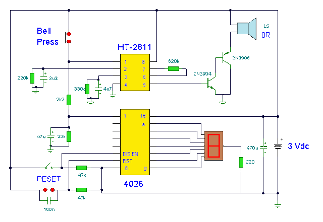
Doorbell with Counter Circuit Diagram

Image
This circuit is a doorbell with counter , that means it counts how many times the bell is triggered . It uses a chip synthesizer sound, the HT -2811 ms nothing prevents you from using another device sound generator . The HT -2811 reproduces the sound of a " ding-dong" doorbell . Besides this ic , the circuit includes a CMOS 4026 and Display Driver IC which counts the total number of visitors .  Electronic Doorbell with Counter Circuit Diagram