Posts

Showing posts with the label In

BASE WIDTH MODULATION IN TRANSISTORS

EARLY EFFECT AND BASE-WIDTH MODULATION IN TRANSISTORS (BJT) A BJT Transistor consisting of three terminals, collector, base, and Emitter and two Junctions, Emitter-Base Junction and Collector-Base Junction. Normally a bipolar Junction Transistor operates on three regions 1. ACTIVE REGION 2. SATURATION REGION 3. CUT-OFF REGION It is well explained in my previous article about Different Operating Modes and Biasing of Transistors,i hope you read it. Now back to our topic, EARLY EFFECT AND BASE-WIDTH MODULATION . In active region, the Emitter-Base Junction is forward biased and Collector-Base Junction is reverse biased, so the barrier width at Emitter-Base Junction is negligible in comparison with the space charge width at Collector-Base Junction. The transition or space-charge region at a Junction is the region of uncovered charges on both sides of the Junction. As the Voltage applied across the Junction increases, the transition region penetrates deeper into the Collector-Base Junction. ...

THERMAL RUNAWAY IN TRANSISTORS

Image
Thermal Runaway and the use of Heat sink in BJT The maximum average power in which a transistor can dissipate depends upon the construction of transistor and lie in the range of few milliwatts and 200W. The maximum power is limited by the temperature that the collector Base junction can withstand. The maximum power dissipation is usually specified for the transistor enclosure is 25 degree celsius. The junction temperature may increase either because of rise in ambient temperature or because of self heating. The problem of self heating arises due to dissipation of power at the collector junction. The leakage current Icbo is extremely temperature dependent and increases with the rise in temperature of collector-base junction. With the increase in collector current Ic, collector power dissipation increases which raises the junction temperature that leads to further increase in collector current Ic. The process is cumulative and may lead to the eventual destruction of transistor. This phe...

Programing UART in ARM Microcontrollers

Image
A UART is usually an individual (or part of an)  integrated circuit  used for  serial communications  over a computer or peripheral device  serial port . UARTs are now commonly included in microcontrollers. A dual UART, or  DUART , combines two UARTs into a single chip. An octal UART or  OCTART  combines eight UARTs into one package, an example being the NXP SCC2698. Many modern ICs now come with a UART that can also communicate synchronously; these devices are called USARTs  (universal synchronous/asynchronous receiver/transmitter). Programing UART in ARM Microcontrollers: you can find here: www.gadgetronicx.com

A Pioneer In Their Own Right The Pioneer Car Stereo

Image
Look at any good car stereo system and you’ll probably see a Pioneer car stereo unit plugged into the console. Alongside with quality speakers and a strong lineup of accessories like LCD panels and navigational devices, Pioneer products/Pioneer car stereos have earned a huge following the world over.   The Pioneer Company is a Tokyo-based corporation, and is one of the world leaders in digital entertainment products. The Pioneer Company was first founded in 1938 in Tokyo as a small radio and speaker repair shop business but today, they are recognized as a leader in technology advancements in the consumer electronics industry. The company is truly deserving of their name. They are respected for many innovations such as interactive cable TV, the Laser Disc player, developing the first Compact Disc player for the car and the first detachable face car stereo, DVD and DVD recording, plasma display, and organic electroluminescent display. Their strength in optical disc and display techn...

Demystifying The Use of Table Pointer in SPWM Application in Sine Wave Inverter

Image
I have previously written quite a few articles on sinusoidal pulse width modulation (SPWM). I've discussed about how to generate the sine table, how to implement it, how to practically generate the SPWM signals (with example code) and also how to implement feedback with simple sine table manipulation with table pointer instead of complex PID control. All these methods have one thing in common regarding the implementation - use of the sine table and its control with the table pointer. Whether you use or implement feedback or not, the table pointer is used to access and retrieve values from the sine table. Before reading or going through this article, I suggest you go through these first: Tutorial (Click here to open tutorial): Generation and Implementation of Sine Wave Table   Article (Click here to open article): Smart Sine – Software to generate sine table Article (Click here to open article): Generation of sine wave using SPWM in PIC16F684 It took quite a while for me to unde...

PIC16F887 877 programming in C Tutorial 7 LCD Moving Display n Custom Characters

Image
LCD; Moving Display & Custom Character : You can display your custom characters by using mikroc custom character tool. Go to tools>>customer character then make the character you want to display. After this click on 'generate code'. It will generate a customchar function just copy and paste above the main function. customchar has two parameters; row and position in that row. Just pass these parameters where you want to see your custom character on LCD. You can also move the text, left and right, on LCD screen; by using the LCD commands. _LCD_SHIFT_LEFT and   _LCD_SHIFT_RIGHT are the commands. There are various other commands in mikroc, i forget to tell you in lcd tutorial, these are: LCD Commands Now lets write a code to display and move the custom character, back and forth, (of your choice) on LCD screen. Code: // LCD module connections sbit LCD_RS at RB4_bit; sbit LCD_EN at RB5_bit; sbit LCD_D4 at RB0_bit; sbit LCD_D5 at RB1_bit; sbit LCD_D6 at RB2_bit; sbit LCD_D7 ...

LEDs IN SERIES PARALLEL

Image
LEDs IN SERIES LEDs can be placed in series providing some features are taken into account. The main item to include is a current-limiting resistor. A LED and resistor is called a string. A string can have 1, 2, 3 or more LEDs. Three things must be observed: 1. MAXIMUM CURRENT through each string = 25mA. 2. The CHARACTERISTIC VOLTAGE-DROP must be known so the correct number of LEDs are used in any string. 3. A DROPPER RESISTOR must be included for each string. The following diagrams show examples of 1-string, 2-strings and 3-strings: LEDs IN PARALLEL LEDs CANNOT be placed in parallel - until you read this: LEDs "generate" or "possess" or "create" a voltage across them called the CHARACTERISTIC VOLTAGE-DROP  (when they are correctly placed in a circuit). This voltage is generated by the type of crystal and is different for each colour as well as the "quality" of the LED (such as high-bright, ultra high-bright etc). This characteris...

Asus PadFone 2 phone in a tablet released with quad core processor and ICS

Image
The PadFone 2 is not only bigger and faster, it is, combined, lighter than Apple's new iPad, add to that one of the most powerful processors in a smartphone and you're onto a winner. Asus has unveiled the new PadFone 2 smartphone and tablet hybrid in Milan today running Ice Cream Sandwich and sporting a larger 4.7-inch HD display and quad-core S4 processor. The PadFone 2 has had a bump in the screen department going up to a Galaxy S3 rivaling 4.7-inches whilst swapping the original OLED panel for an integrated Super LCD which means brighter, sharper and as we've seen in the iPhone 5, a lot thinner. Under the hood is where things get really impressive however as the PadFone 2 sports Snapdragon's new S4 quad-core processor making it one of the most powerful smartphones on the market. There's 2GB of RAM making sure that no matter what you're doing the PadFone 2 won't even break a sweat. The camera has been given a massive boost now offering up 13MP along with F...

Explanation of Errors in Moving Coil Instruments

Errors in Moving Coil Instruments The errors that usually occur in PMMC instruments are 1.        The frictional error. 2.        Temperature error. 3.        The error owing weakening of permanent magnet. 4.        Stray magnetic field error. 5.        Thermo-electric error. 6.        Observational error. 1.        The frictional Error: The friction of the pivot in the jewel produces a frictional torque which affects the instrument reading. This error is more serious for sensitive instruments designed for low operating torque. Remedy: The frictional error in PMMC instruments can be produced by providing proper pivoting and balancing i.e. these errors may be reduced by adopting a moving system of light construction and large deflecting torque. 2.      ...

Ultrasonic Sensor Applications in Automation industry

Image
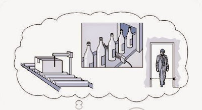
Ultrasonic Sensor Applications in Automation industry There are many numbers of applications where sensors can be utilized, and as you have seen throughout this book there are a number of sensors to choose from. Choosing the right sensor can be confusing and takes careful thought and planning. Often, more than one sensor will do the job. As the application becomes more complex the more difficult it is to choose the right sensor for a given application. The following application guide will help you find the right sensor for the right application.  Ultrasonic Sensor Applications in Automation industry  

Connecting Two or More Transistors in Parallel

Image
How to Connect two or more transistors in parallel While making power electronic circuits, configuring the power output stage correctly becomes very crucial. These stages primarily may consist of power devices like the power transistors or MOSFETs. Using power transistors are more common due to the greater ease of  configuring them. However when higher outputs are desired, it becomes necessary to add more number of these devices together. And as per the rules, it becomes necessary to connect them in parallel. Though using transistors in electronic circuits is pretty easy, connecting them in parallel needs some attention due to the one significant drawback with transistor characteristics. As per transistor specs, the devices needs to be operated under reasonably cooler conditions and that's why we install heatsinks on them to maintain the above criterion. Moreover, transistors have the "bad habit" of conducting proportionately rising currents through them as they get heate...