Posts

Showing posts with the label Cost

Low Cost Stereo Level Indicator Circuit Diagram

Image
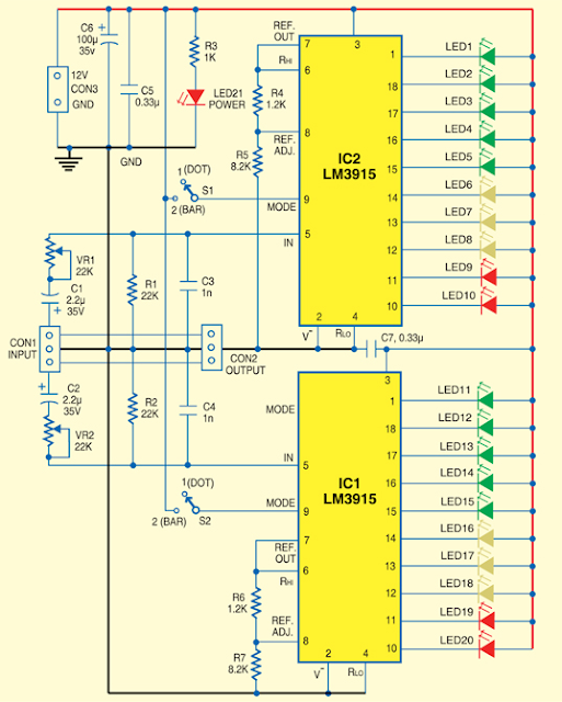
Usually, Low-Cost Stereo Level Indicator home stereo power amplifiers don’t have output level indicators . An output power level indicator can be added to each channel of these stereo power amplifiers . As low levels of the output power are not disturbing and damaging to the people, there is no need to add a preamplifier and low-level detector before IC LM3915. But you should know when the output power becomes considerably high. Here we present a very simple, low-cost stereo-level indicator circuit for home power amplifiers with power rating of around 0.5W. The circuit is built around two LM3915 dot/bar display driver ICs (IC1 and IC2). LM3915 senses analogue voltage levels to drive ten LEDs, providing a logarithmic 3dB/step analogue display. Stereo Level Indicator Circuit Diagram The voltage levels below 1V are not important because these correspond to a low level of the audio signal. Similarly, input voltage levels above 30V correspond to too high levels of the output power, which ...

500W low cost 12V to 220V inverter

Image
Using this circuit you can convert the 12V dc in to the 220V Ac. In this circuit 4047 is use to generate the square wave of 50hz and amplify the current and then amplify the voltage by using the step transformer.   Circuit diagram   How to calculate transformer rating The basic formula is P=VI and between input output of the transformer we have Power input = Power output For example if we want a 220W output at 220V then we need 1A at the output. Then at the input we must have at least 18.3V at 12V because: 12V*18.3 = 220v*1 So you have to wind the step up transformer 12v to 220v but input winding must be capable to bear 20A. author: Ashad Mustufa e-mail: mustufa66@hotmail.com Source : http://www.electronics-lab.com

Low Cost Step Down Converter

Image
The circuit described here is mostly aimed at development engineers who are looking for an economical step-down converter which offers a wide input volt-age range. As a rule this type of circuit employs a step-down converter with integrated switching element. However, by using a more discrete solution it is possible to reduce the total cost of the step-down converter, especially when manufacturing in quantity. The TL5001A is a low-cost PWM controller which is ideal for this project. Low Cost Step Down Converter with Wide Input Voltage Range The input voltage range for the step-down converter described here is from 8 V to 30 V, with an output voltage of 5 V and a maximum output current of 1.5 A. When the input voltage is applied the PWM output of IC1 is enabled, taking one end of the voltage divider formed by R1 and R2 to ground potential. The cur-rent through the voltage divider will then be at most 25 mA: this value is obtained by dividing the maximum input voltage (30 V) minus t...

Step Down Converter With Wide Input Voltage Range

Image
The circuit described here is mostly aimed at development engineers who are looking for an economical step-down converter which offers a wide input voltage range. As a rule this type of circuit employs a step-down converter with integrated switching element. However, by using a more discrete solution it is possible to reduce the total cost of the step-down converter, especially when manufacturing in quantity. The TL5001A is a low-cost PWM controller which is ideal for this project. The input voltage range for the step-down converter described here is from 8 V to 30 V, with an output voltage of 5 V and a maximum output current of 1.5 A. When the input voltage is applied the PWM output of IC1 is enabled, taking one end of the voltage divider formed by R1 and R2 to ground potential. The current through the voltage divider will then be at most 25 mA: this value is obtained by dividing the maximum input voltage (30 V) minus the saturation voltage of the output driver (2 V) by the total resi...