Posts

Showing posts from March, 2017

Stereo 175 watt amplifier or 350 watt mono amplifier STA517B

Image
350 watt mono amplifier Stereo circuit in datasheet here

Mini and simple power amplifier circuits

Image
What is the meaning of the picture above? The above picture is a miniature audio amplifier and very simple. Here I will give an audio amplifier schematic is very simple which only requires a few components only, can be seen under this scheme. See from above scheme may occur to you, certainly cheap enough to make this amplifier and quite easy to make. The above simple audio amplifier circuit using an IC as the main amplifier and accompanied by other components. IC used is S1513, which requires a supply voltage ranging from 1.5 volts to 6 volts. And only 0.1 W output power with 4 ohm impedance. For a list components can be seen below. Part list C1 = 100nF C2 = 100uF C3 = 3n3F C4 = 1uF C5 = 1uF U1 = S1513

Laser Controlled ON OFF Switch Circuit Diagram

Image
This circuit is built around a 555 timer using very few components. Since the circuit is very simple, even a novice can easily build it and use it as a controlling device. A laser pointer, now easily available in the market, can be used to operate this device. This circuit has been tested in operational conditions from a distance of 500 meters and was found to work satisfactorily,though it can be controlled from still longer distances. Circuit diagram : Laser Controlled ON/OFF Switch Circuit Diagram Aiming (aligning) the laser beam exactly on to the LDR is a practical problem. The circuit is very useful in switching on/off a fan at night without getting off the bed. It can also be used for controlling a variety of other devices like radio or music system. The limitation is that the circuit is operational only in dark or dull lit environments. By focusing the laser beam on LDR1 the connected gadget can be activated through the relay, whereas by focusing laser beam on LDR2 we can switch

Ultrasonic Sensor Applications in Automation industry

Image
Ultrasonic Sensor Applications in Automation industry There are many numbers of applications where sensors can be utilized, and as you have seen throughout this book there are a number of sensors to choose from. Choosing the right sensor can be confusing and takes careful thought and planning. Often, more than one sensor will do the job. As the application becomes more complex the more difficult it is to choose the right sensor for a given application. The following application guide will help you find the right sensor for the right application.  Ultrasonic Sensor Applications in Automation industry  

Build a Voltage to Frequency Converter Circuit Diagram 3

Image
Build a Voltage to Frequency Converter Circuit Diagram 3 . The input voltage, V1, causes C1 to charge and produce a ramp voltage at the output of the 741 op amp. Diodes D1 and D2 are four-layer devices. When the voltage across C1 reaches the breakover voltage of either diode, the diode conducts to discharge C1 rapidly and the op amp output goes abruptly to zero. This rapid discharge action applies a narrow pulse to G1 and G2. Positive discharge pulses produced by a positive V1 are coupled to the output only through G1, while negative pulses are coupled only through G2.  Because of the forward break-over current of diodes D1 and D2, the circuit won`t operate below a minimum input voltage. An increase of R1 increases this minimum voltage and reduces the circuit`s dynamic range. The minimum input voltage with R1 at 1 Kn is in the range of 10 to 50 m V. This input dead zone, when input signal V1 is near zero is desirable in applications that require a signal to exceed a certain level befor

Simple Power supply without transformer

Image
This circuit has a voltage output of about 12 volts with 20mA current voltage. And this series of works using capacitive reactance and resistance are not using, this will reduce the heat on the circuit. To be safe when there is a short-circuit series, always use a fuse on the input voltage is 220V. Here is a series of power supply without a simple transfomer. Power supply Circuit Part List R1 - 1.8K 1W R2 - 100Ω C1 - 0.47µF 400V C2 - 1000µF 50V D1 - 1N4007 D2 - 1N4007 D3 - 1N4007 D4 - 1N4007 ZD1 - 16V Zener Diode ZD2 - 16V Zener Diode ZD3 - 12V Zener Diode

Door Phone Circuit Schematic Diagram

Image
Circuit Schematic Diagram Description This circuit can be used in front doors for visitors to communicate or it can be wired up in the front gate for conversation, this circuit is fairly simple but its worth, it dose not use any sought of condenser mic for voice transmission if uses the speaker for both the transmission purpose and for the reception purpose, the heart of the circuit is the operational amplifier LM386 which is used to amplify the voice signal gain adjust is provided by the 5k preset and the pot resistor 10k is used as the volume control. Source - http://www.electronguide.com/circuits_pages/Doorphonecircuit.html

USB Powered PIC Programmer

Image
This simple circuit can be used to program the PIC16F84 and similar "flash memory" type parts. It uses a cheap 555 timer IC to generate the programming voltage from a +5V rail, allowing the circuit to be powered from a computer’s USB port. The 555 timer (IC1) is configured as a free-running oscillator, with a frequency of about 6.5kHz. The output of the timer drives four 100nF capacitors and 1N4148 diodes wir-ed in a Cockroft-Walton voltage multiplier configuration. USB-Powered PIC Programmer Circuit diagram: USB-Powered PIC Programmer Circuit Diagram The output of the multiplier is switched through to the MCLR/Vpp pin of the PIC during programming via a 4N28 optocoupler. Diodes ZD1 and D5 between the MCLR/Vpp pin and ground clamp the output of the multiplier to about 13.6V, ensuring that the maximum input voltage (Vihh) of the PIC is not exceeded. A 100kΩ resistor pulls the pin down to a valid logic low level (Vil) when the optocoupler is not conducting. The circuit is compa

nScope a lab for every laptop

Image
nScope is a usb-powered device that plugs into an electronics prototyping breadboard. nScope’s main function is an oscilloscope. Much like a multimeter, an oscilloscope measures voltages in a circuit. But unlike a multimeter, it stores voltages over time and displays them in a graph. This makes nScope much more useful for observing sensor signals and dynamic circuits. nScope’s software interface maximizes the graph space, and provides controls for setting the measurement speed and range. [ ]

12V to 220V Inverter Schematics

Image
12V to 220V Inverter Circuit Diagrams, Even though today’s electrical appliances are increasingly often self-powered, especially the portable ones you carry around when camping or holidaying in summer, you do still sometimes need a source of 230 V AC - and while we’re about it, why not at a frequency close to that of the mains? As long as the power required from such a source remains relatively low - here we’ve chosen 30 VA - it’s very easy to build an inverter with simple, cheap components that many electronics hobbyists may even already have 12V to 220V Inverter . 12V to 220V Inverter Circuit Diagrams Though it is possible to build a more powerful circuit, the complexity caused by the very heavy currents to be handled on the low-voltage side leads to circuits that would be out of place in this summer issue. Let’s not forget, for example, that just to get a meager 1 amp at 230 VAC , the battery primary side would have to handle more than 20 ADC !. The circuit diagram of 12V to 2

Toshiba Excite 7 Android Tablet Announced

Image
Toshiba has announced Excite 7, its latest Android tablet. If you’re looking for a balance option between price and performance, the 7-inch tablet may be able to catch your eyes. Toshiba Excite 7 is a budget friendly and high performance Android tablet that runs on Google Android 4.2.2 Jelly Bean mobile operating system. The Android tablet is powered by Rockchip RK3188 quad-core processor, and comes with 1GB RAM, 8GB eMMC internal storage, 7-inch capacitive 5-finger multi-touchscreen LCD display with 1024 x 600 pixels resolution, 0.3-megapixel front-facing webcam and 3-megapixel rear camera. Moreover, other specs also include WiFi, Bluetooth 4.0, microSD card slot, stereo speakers and 14W-hours rechargeable battery for up to 8 hours of video playback. Toshiba Excite 7 Android tablet is priced at $169.99 USD. If you’re interested, jump to Toshiba official site for more details.

Steam Whistle Circuit Diagram

Image
This is a simple Steam Whistle Circuit Diagram. This circuit consists of six square wave oscillators. Square waves are made up of a large number of harmonics. If six square waves with different frequencies are added together, the result will be a signal with a very large number of frequencies. When you listen to the result you’ll find that it is very similar to a steam whistle. The circuit should be useful in modelling or even in a sound studio. Steam Whistle Circuit Diagram Simple Steam Whistle Circuit Diagram This circuit uses only two ICs. The first IC, a 40106, contains six Schmitt triggers, which are all configured as oscillators. Different frequencies are generated by the use of different feedback resistors. The output signals from the Schmitt triggers are mixed via resistors. The resulting signal is amplified by IC2, an LM386. This IC can deliver about 1 W of audio power, which should be sufficient for most applications. If you leave out R13 and all components after P1, the out

Water Alarm Circuit Diagram

Image
The LM1830 fluid detector IC from National Semiconduc tor is designed to be able to detect the presence of fluids using a probe. This chip requires a relatively high supply voltage and is not the most frugal power consumer. It is also quite specialised so unless you are buying in bulk the one-off price is not cheap.  An alternative circuit show n her e uses a standard CMOS IC type 74HC14. It has the advantage of operating with a 3 V supply and consumes less than 1 µA when the alarm is not sounding, this makes it ideal for use with batteries.  Water Alarm Schematic Circuit Diagram The 74HC14 has six inverters with hysteresis on their input switching thresholds. A capacitor (C1) and a feedback resistor (R1) is all that’s necessary to make an inverter into a square wave signal generator.  In the water alarm circuit the feedback resistor consists of R1 and the water sensor in series. R1 prevents any possibility of short-circuit between the inverter’s input and out-put. Resistor R2 defines

7 SEGMENT DISPLAY COUNTER INCOMING PERSON COUNTER

Image
Hiii…….friends today I am here with a very interesting projects for those who have just started with electronics. With this project we can display 0-9 digits on the 7 segment and we can count the no of persons entering in a room.  Circuit Diagram Here a counter IC 7490 is used along with BCD to 7 segment decoder IC 7447. The function of 7490 is to provide the counting value and decoder IC is decoding that value to 7 segment output . Every time when you will push the switch the clock of IC7490 will be triggered and as a result count will increase by 1 . Hence with this simple project we can display numbers 0 to 9 on seven segment display just by pressing switch. It’s a very easy circuit and you can easily implement it on a general purpose PCB . NOW ITS TIME TO MAKE USE OF THIS CIRCUIT IN COUNTING THE NUMBER OF PERSONS ENTERING IN THE ROOM...... LETS SEE HOW….?? So instead of using switch we will use LDR here , we will place LDR at the entry door in such a manner that the shadow of the e

Streampowers PC Power Box with E fuse

Image
This little circuit can assist you to get rid of all surplus tiny ac mains adaptors from your desktop. The circuit is nothing, however a sensible dc power box directly powered by the smps of your desktop pc. Regulated, clean and guarded +12VDC is offered at the output of this unit. additionally, a USB power port is provided to re-charge transportable devices as well as cellphones and music players, etc. How will the computer power box works All you would like is to open your system box and connect an unused 4-pin drive power connector from the system smps to the current circuit. +12V (Yellow wire) from the smps is processed by a resettable electronic fuse designed around elements T1, T2 and T3 and feed to the output terminal. equally the +12V is down converted to stable +5V by fastened three pin regulator IC1. Smart dc power box circuit schematic As a result, +12V (500 -750mA max, based mostly on the electrical characteristics of T2 used) and +5V (1A max) DC provides are obtainable fo

Generate Electricity from Body Heat Circuit Diagram

Image
The operating principle of this design is unique and extremely simple, the most critical component is the one ba7891 tunnel diode, the circuit that are seven or more soldiers in series and connected to a heat sink large. The sink will serve to accumulate thermal energy, which can be the sun, a fire, the body or any other form of heat energy which is converted into a charge current for NiCd battery. A tunnel diode is very different from a normal rectifier diode and is characterized by a quick response time, another feature and negative resistance, basically, is explored in this circuit with the purpose of generating electricity from the heat.   Generate Electricity from Body Heat Circuit Diagram

CAUSE AND EFFECT DIAGRAM

Image
Ishikawa diagram, in fishbone ... Fishbone Diagram Cause-and-Effect Diagram Cause and effect diagram The usefulness of a Fishbone ... Cause and effect diagram for ... 5. Drill Down on Causes These diagrams are now often ... Fishbone Diagram Example ... cause has been identified.

Mini Amplifier with 3 Transistor

Image
Mini 3 transistor amplifier is a simple amplifier with 50mW power drawn by 3 transitor. The series of three mini-amplifier transistors can be used for loud speaker 8 ohm load. Source voltage required to activate the mini-amplifier can be drawn from the batteries 9V.Rangkaian 3 transistor amplifier is often used in simple portabe audio devices such as radios or small tape recorder. Mini-transistor amplifier circuit 3 is quite simple as shown in the figure below. Mini-transistor amplifier circuit 3 includes type of amplifier OTL (Output Transformer Less). Mini-transistor amplifier circuit 3 is used for output coupling capacitors. Amplifier circuit is simple and suitable when used for audio amplifier experiment.

Dual Tracking regulator circuit

Image
A IC MAX634 inverting regulator is combined with a IC MAX630 to provide a dual tracking approximately 15 Volt output from a 12 Volt DC battery. The reference for the - 15 Volt output is derived from the positive output via R3 and R4. Both regulators are set to maximize output power at low battery voltages by reducing the oscillator frequency , via LBR, when V Batt falls to 8,5 volt. Technical instruction : Max. Input voltage    : 13 Volt / N/a mA Max. Output voltage :-15 Volt , + 15 volt / 45 mA

Multitasking Pins

Image
It’s entirely logical that low-cost miniature microcontrollers have fewer ‘legs’ than their bigger brothers and sisters – some-times too few. The author has given some consideration to how to economise on pins, making them do the work of several. It occurred that one could exploit the high-impedance feature of a tri-state output. In this way the signal produced by the high-impedance state could be used for example as a CS signal of two ICs or else as a RD/WR signal. Multitasking Pins  Schematic All we need are two op-amps or comparators sharing a single operating voltage of 5 V and outputs capable of reaching full Low and High levels in 5-V operation (preferably types with rail-to-rail outputs). Suitable examples to use are the LM393 or LM311.The resistances in the voltage dividers in this circuit are uniformly 10 kilohms. Consequently input A lies at half the operating voltage (2.5 V), assuming nothing is connected to the input or the microcontroller pin connected is at high impe

Simple Mains Frequency Monitor Circuit Project

Image
Project of Mains Frequency Monitor Circuit Diagram. Here is a simple frequency counter designed to monitor the 240VAC mains supply. It as a frequency range of 0-999Hz, so it could also be used with 400Hz equipment. Standard TTL/CMOS logic is employed for the counters and display drivers, while an ELM446 (IC1) generates accurate 1Hz pulses for gating. This device utilizes a 3.579545MHz crystal for its timebase, as commonly found in TV and video circuits and even on old PC motherboards. Mains Frequency Monitor Circuit Diagram : Mains Frequency Monitor Circuit Diagram Copyright: Silicon Chip Electronics Magazine

Reliable Car Battery Tester

Image
This circuit uses the popular and easy to find LM3914 IC. This IC is very simple to drive, needs no voltage regulators (it has a built in voltage regulator) and can be powered from almost every source. This circuit is very easy to explain: When the test button is pressed, the Car battery voltage is feed into a high impedance voltage divider. His purpose is to divide 12V to 1,25V (or lower values to lower values). This solution is better than letting the internal voltage regulator set the 12V sample voltage to be feed into the internal voltage divider simply because it cannot regulate 12V when the voltage drops lower (linear regulators only step down). Simply wiring with no adjust, the regulator provides stable 1,25V which is fed into the precision internal resistor cascade to generate sample voltages for the internal comparators. Anyway the default setting let you to measure voltages between 8 and 12V but you can measure even from 0V to 12V setting the offset trimmer to 0 (but i think

Telephone Ringing

Image
Telephone Ringing circuit Diagram . Even though cordless phones have invaded our homes and offices, you don’t always have them at hand, and as their ringtones are usually very much quieter than the old rotary-dial- type analogue phones, it can happen that you miss a call you’ve been waiting for while you’ve been going about your daily business.  Until quite recently, you could still find remote ringers that could be plugged into any standard phone socket in order to have an additional ringer, but it seems as if these accessories are currently being phased out as everyone is ‘going cordless’. So we decided to suggest something better, with this phone ring repeater that makes it possible to control any device connected to the AC power outlet using the ringtone available on any subscriber line, and naturally, with all the guarantees of safety and isolation that are of course rightly expected. So it’s capable of driving a ringer, or indeed even a high-powered sounder to alert you when you

CadSoft Eagle Professional 6 5 0 Multilingual 44 27 MB

Image CadSoft Eagle Professional 6.5.0 Multilingual | 44.27 MB EAGLE (Easily Applicable Graphical Layout Editor) is an ECAD program produced by Cadsoft in Germany. It is very commonly used by private electronics enthusiasts, because there is a very usable free demo version for nonprofit use and is available in English and German. Cadsoft has released versions for Microsoft Windows, Linux, and Mac OS X. EAGLE provides a schematic editor, for designing circuit diagrams and a tightly integrated PCB layout editor, which automatically starts off with all of the components required by the schematic. Components are manually arranged on the board, with the help of coloured lines showing the eventual connections between pins that are required by the schematic, to aid in finding a placement that will allow the most efficient track layout. It also provides a good autorouter, which once the components have been placed will attempt to automatically find an optimal track layout to make the electrica

Simple relay diagram

Image

Magnetic Reed Switch Alarm

Image
This circuit is made to be an alarm, both for home and handbags. If it is installed for home it will placed on door or windows, and if it is installed for bags or handbags it will placed in the bag. This circuit consists of a small magnet and a reed switch. If the magnet looses its contact with the reed switch, SW1 opens, the circuit starts oscillating and the loudspeaker emits a loud alarm sound.so this circuit suitable for use as an anti-theft alarm. This circuit uses A complementary transistor-pair which is wired as a high efficiency oscillator, directly driving a small loudspeaker. Low part-count and 3V battery supply enable a very compact construction. Notes : The loudspeaker’s dimensions are limited only by the box that contain it. An on-off switch is unnecessary because the stand-by current drawing is less than 20µA. Current consumption when the alarm is sounding is about 100mA. If the circuit is used as anti-bag-snatching, SW1 can be replaced by a 3.5mm mono Jack socket and the

Low voltage Power Supply Circuit Diagram

Image
If you want to check the behaviour of an electronic circuit at low voltages, an adjustable power supply as shown here may be helpful. Powered from a 3 to 16 volts source (DC for sure), it will provide a stable output voltage in the 0 to 1.5 V range. Adjustable Low-voltage Power Supply Circuit Diagram Multiturn trimpot P1 allows the output volt-age to be adjusted with good precision. The BC337-400 output transistor raises the out-put current to about 200 mA bearing in mind that the minimum supply voltage is 3.5 V. The transistor’s dissipation should be taken into account, and a more power ful t ype used if necessary. T1 may be omitted and R2 replaced with a wire link if you are happy with 3 mA at 3 volts out, 10 mA at 6 V or 20-30 mA at 10-16 V. These values represent the maximum output current of the TLC271 op amp. Without T1, the minimum supply voltage is 3.0 V. Author:Vladimir Mitrovic - Copyright: Elektor

Hofner Colorama II restoration project part 3 re fretting the guitar neck

Image
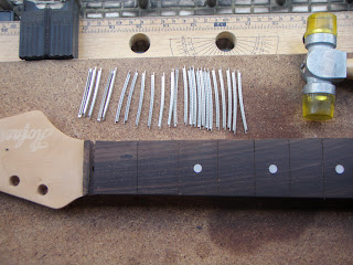
In the last blog post, we stripped down and de-fretted a vintage Hofner Colorama II neck. Today we’ll re-fret it. First of all, we need to do some initial preparation, so we lay the neck out on its jig just like in the previous post and then sort out the fret wire. These frets have been bought pre-cut and pre-radiused. They’re not all the same length, so we need to sort them in order of shortest to longest. Here we’ve punched holes (don’t use the frets to do this!) in an empty cardboard box and placed the frets in them in the correct order. Next thing we need to do is clean all of the dust, etc., out of the fret slots. A thin craft knife will suffice for this, but do it in the opposite direction to the knife edge (in other words, if the blade is pointing forwards, then pull the knife backwards). Remember, we’re not actually cutting anything here, just pushing all of the dust out of the slots. Next we take our shortest fret and do a test fitting in the first fret slot. Uh-oh, it seems t