Posts

Showing posts with the label Bass

Simple Accurate Bass Tone Control

Image
A difficult problem in the design of conventional stereo tone controls is obtaining synchronous travel of the potentiometers. Even a slight error in synchrony can cause phase and amplitude differences between the two channels. Moreover, linear potentiometers are often used in such controls, and these give rise to unequal performance by human hearing. Special potentiometers that counter these difficulties are normally hard to obtain in retail shops. A good alternative is a control based on a rotary switch and a discrete potential divider. The problem with this that for good tone control more than six steps are needed, and switches for this are also not readily available. Fortunately, electronic circuits can remove these difficulties.     The analogue selectors used may be driven by mechanical switches, standard logic circuit or a microcontroller. The selectors used in the present circuit are Type SSM2404 versions from Analogue Devices, which switch noiselessly. Each IC contains...

Vocal Adaptor for Bass Guitar Amp

Image
These days, music is a major hobby for the young and not-so-young. Lots of people enjoy making music, and more and  more dream of showing off their talents on  stage. But one of the major problems often encountered is the cost of musical equipment. How many amateur music groups sing through an amp borrowed from a guitarist or bass player?  This is where the technical problems arise not in terms of the .25” (6.3 mm)  jack, but in terms of the sound quality (the words are barely understandable) and volume (the amp seems to produce fewer decibels than for a guitar). What’s more, unpredictable feedback may cause damage to the speakers and is very unpleasant on the ear. This cheap little easy-to-build project can help solve these technical problems. A guitar (or bass guitar) amplifier is designed first and foremost to reproduce the sound of the guitar or bass as faithfully as possible. The frequency response of the amp doesn’t need to be as wide or as flat as in hi-fi (p...

Bass Booster with TL072

Image
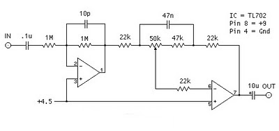
The following is megabass circuit schematic (rangkaian megabass) . The megabass circuit is a modified Baxandall tone control with no bass cut and no treble control. It boosts frequencies from about 30Hz to 160Hz can boost by 14dB. Bass Booster Schematics Note: The input capacitor can be replaced with a .01uf cap if you wish. The 10pf capacitor is optional and will start rolling off everything over 15kHz. 5pf will double this to 31kHz. The tone control requires a low impedence input. If you already have a low impedence input, the input buffer can be removed. However, the output is inverted. The opamp is not critical. A 4558 would be just fine. I do not show the parts for the +4.5 reference. Here is the +4.5 voltage divider I used. IC A4558 Pinning The A4558 is a monolithic Integrated Circuit designed for dual operational amplifier. Absolute maximum ratings of A4558 Ap-amp Supply voltage VCC 20 or ±10 V Differential input voltage VIND 20 V Input voltage VIN ±10 V Power Dissipation PD 300...

Adaptor for Bass Guitar Amp

Image
Adaptor for Bass Guitar Amp . These days, music is a major hobby for the young and not-so-young. Lots of people  enjoy  making  music,  and  more  and  more dream of showing off their talents on stage. But one of the major problems often encountered is the cost of musical equipment. How many amateur music groups sing  through an amp borrowed from a guitarist or bass player?  This is where the technical problems arise not in terms of the .25” (6.3 mm)  jack, but in terms of the sound quality (the words  are barely understandable) and volume (the amp  seems to produce fewer decibels than for a guitar). What’s more, unpredictable feedback may cause damage to the speakers and is very unpleasant on the ear. This cheap little  easy-to-build project can help solve these technical  problems. . Circuit diagram : Vocal Adaptor for Bass Guitar Amp Circuit Diagram A guitar (or bass guitar) amplifier is designed first and foremos...

10W Audio Amplifier with Bass boost

Image
This Audio Amplifier design is based on the audio amplifier 18 watts, and was developed primarily to meet the requests of correspondents unable to locate the chip TLE2141C. It uses the NE5532 Dual IC wide, but obviously, its power output will be written in the 9.5 - 11.5W range, as the supply rails can not exceed ± 18V. As amplifiers of this type are often used to drive small loudspeaker cabinets, the bass frequency range is rather sacrificed. Therefore, a Bass Boost control was inserted in the amplifier feedback loop, in order to overcome this problem, without loss of quality. The low elevation curve can reach a maximum of 16.4 dB @ 50Hz. In any case, even when the bass control is turned fully counterclockwise, the amplifier's frequency response curve shows a gentle rise: 0.8 dB at 400 Hz, 4.7 dB at 100 Hz and 6 dB at 50 Hz (referred to 1 kHz).