Posts

Showing posts with the label relay

Light Activated Relay

Image
This is same circuit as above with the addition of a photo resistor to trigger the flip flop instead of a push button. The bias resistor in series with photo resistor was chosen so that sufficient voltage is present at the base of the 2N3904 to supply current to the circuit in ambient lighting conditions. The circuit should toggle when the photo resistor is hit by a flashlight beam or other fast changing light source. Slow changes in light intensity will have no effect unless the light gets too bright to maintain sufficient bias for the 2N3904. Light Activated Relay Circuit diagram :

operating characteristics of an impedance relay on an R X diagram

Image

Simple Power Saving Relay Driver Circuit Diagram

Image
In many circuits, the switching action is performed by a relay, which in turn activates an external load. The power consumed by the relay may be unsuitable for battery-powered applications. Here is a simple solution using some inexpensive components to considerably save power. Circuit and working Fig. 1 shows circuit diagram of the power-saving relay driver where resistor R1 and transistor T1 form a standard relay driver circuit. Power-Saving Relay Driver Circuit Diagram Once the relay is energised, its pole is pulled in to make contact with the N/O side, and it holds in that position with typically 75 per cent of its nominal-rated voltage. Power consumed by a relay coil during this holding time equals V²/R, where R is resistance of the relay coil and V is the voltage. Here resistors R2 and R3, transistor T2 and capacitor C1 lower the power consumption after actuation by applying less than the normal operating power. Initially, when power is applied, capacitor C1 momentarily shorts res...

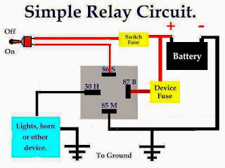
Simple relay diagram

Image

Simple PIC Controlled Relay Driver Circuit Diagram

Image
This is a simple project of PIC Controlled Relay Driver circuit is a relay driver that is based on a PIC16F84A microcontroller. The board includes four relays so this lets us to control four distinct electrical devices. The controlled device may be a heater, a lamp, a computer or a motor. To use this board in the industrial area, the supply part is designed more attentively. To minimize the effects of the ac line noises, a 1:1 line filter transformer is used. The transformer is a 220V to 12V, 50Hz and 3.6VA PCB type transformer. The model seen in the photo is HRDiemen E3814056. Since it is encapsulated, the transformer is isolated from the external effects. A 250V 400mA glass fuse is used to protect the circuit from damage due to excessive current. A high power device which is connected to the same line may form unwanted high amplitude signals while turning on and off. To bypass this signal effects, a variable resistor (varistor) which has a 20mm diameter is paralelly connected to the...

Water Pump Relay Controller Circuit Schematic

Image
Description By means of a Relay, employed to drive a water pump, this circuit provides automatic level control of a water reservoir or well. The shorter steel rod is the "water high" sensor, whereas the longer is the "water low" sensor. When the water level is below both sensors, IC1C output (pin #10) is low; if the water becomes in contact with the longer sensor the output remains low until the shorter sensor is reached. At this point IC1C output goes high, Q1 conducts, the Relay is energized and the pump starts operating. Now, the water level begins to decrease and the shorter sensor will be no longer in contact with the water, but IC1C output will be hold high by the signal return to pin #5 of IC1B, so the pump will continue its operation. But when the water level falls below the longer sensor, IC1C output goes low and the pump will stop. SW1 is optional and was added to provide reverse operation. Switching SW1 in order to connect R3 to pin #11 of IC1D, the pump ...

Restricted earth fault protection connected earth fault relay

Image