Posts

Showing posts with the label or

Schematic Power Amplifier with IC AN7114 or AN7115

Image
This Circuit must use the IC AN7114 or you can use the IC AN7115 . Minimum voltage for this IC is 6 Volt and maximum voltage is 11 . You can supply this Circuit with 12 Volt if  you use IC AN7115 because its maximum voltage 13 volt. Output Power 1 watt with Impedance 4 ohm .   See the Schematic (figure 2.0) and package IC ( figure 1.0 ) : Figure 1.0 Figure 2.0

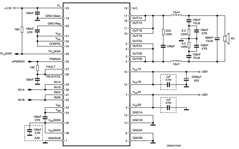
Stereo 175 watt amplifier or 350 watt mono amplifier STA517B

Image
350 watt mono amplifier Stereo circuit in datasheet here

Connecting Two or More Transistors in Parallel

Image
How to Connect two or more transistors in parallel While making power electronic circuits, configuring the power output stage correctly becomes very crucial. These stages primarily may consist of power devices like the power transistors or MOSFETs. Using power transistors are more common due to the greater ease of  configuring them. However when higher outputs are desired, it becomes necessary to add more number of these devices together. And as per the rules, it becomes necessary to connect them in parallel. Though using transistors in electronic circuits is pretty easy, connecting them in parallel needs some attention due to the one significant drawback with transistor characteristics. As per transistor specs, the devices needs to be operated under reasonably cooler conditions and that's why we install heatsinks on them to maintain the above criterion. Moreover, transistors have the "bad habit" of conducting proportionately rising currents through them as they get heate...

LEDs or Lamps Sequencer

Image
Very simple, versatile modular design No limits to the number of modules used in the ring Circuit diagram using LEDs:                             Circuit diagram using Lamps: Parts: R1 1K5 1/4W Resistor R2 680R 1/4W Resistor (Optional, see text) C1 47µF 25V Electrolytic Capacitor D1 LED any type Q1 BC337 45V 800mA NPN Transistor P1 SPST Pushbutton LP1 Filament Lamp 12 or 24V (See text) Comments: The purpose of this circuit was to create a ring in which LEDs or Lamps illuminate sequentially. Its main feature is a high versatility: you can build a loop containing any number of LEDs or Lamps, as each illuminating device has its own small circuit. The diagrams show three-stage circuits for simplicity: you can add an unlimited number of stages (shown in dashed boxes), provided the last stage output was returned to the first stage input, as shown. P1 pushbutton p...

DC or AC Voltage Indicator Circuit

Image
Description    This circuit is not a novelty, but it proved so useful, simple and cheap that it is worth building. When the positive (Red) probe is connected to a DC positive voltage and the Black probe to the negative, the Red LED will illuminate. Reversing polarities the Green LED will illuminate. Connecting the probes to an AC source both LEDs will go on. The bulb limits the LEDs current to 40mA @ 220V AC and its filament starts illuminating from about 30V, shining more brightly as voltage increases. Therefore, due to the bulb filament behavior, any voltage in the 1.8 to 230V range can be detected without changing component values. Circuit diagram:  Parts: P1 = Red Probe P2 = Black Probe D1 = 5 or 3mm. Red LED D2 = 5 or 3mm. Green LED LP = 1220V 6W Filament Lamp Bulb Note:    A two colors LED (Red and Green) can be used in place of D1 & D2. Source http://www.extremecircuits.net/2009/08/dc-or-ac-voltage-indicator-circuit.html