Posts

Showing posts with the label Regulator

7805 Voltage Regulator Circuit Diagram

Image
A voltage regulator is used to produce a constant linear output voltage. It’s generally used with AC to DC power supply. And also it can be used as well as a DC to DC voltage converter . To regulating low voltage, most used device is one single IC. 7805, 7812, 7905 etc. 78xx series are design for positive and 79xx series are for Negative voltage regulator. 7805 is a three terminal +5v voltage regulator IC from 78XX chips family. See 7805 pinout below. LM78XX series are from National Semiconductor. They are linear positive voltage regulator IC; used to produce a fixed linear stable output voltage.  National Semiconductor has also negative voltage regulator chips family, they indicate with LM 79XX. 78xx is used more than 79xx because negative voltage has a few usability purposes as we see. I was previously posted a 5v regulated power supply circuit using 7805 IC , that circuit and this 7805 voltage regulator circuit is almost the same. 7805 Voltage Regulator Circuit Diagram ...

Monolithic Step Down Switching Regulator

Image
L4962 is a monolithic step-down  switching regulator. It provides  output voltage of 5.1V to maxi-mum 40V, delivering current up to  1.2A to 1.5A, depending on the type  and package. The theoretical internal  functions are almost the same. The  heart  of  the  device  is  the  regulation  loop  consisting  of  a  saw  tooth  oscillator, error amplifier, comparator and  source-sink output stage. Monolithic Step-Down Switching Regulator Circuit diagram :  Fig. 1: Circuit of switching regulator An error signal is produced by  comparing  the  output  voltage  with  a precise 5.1 volt on chip reference  (which is zener zap trimmed to ±2  per cent). This error signal is then  compared  with  the  saw  tooth  signal  to generate the fixed frequency pulse  width  modulated  pulses  which  driv...

Regulator for Three Phase Generator

Image
This regulator was designed for use with a  generator with a higher output voltage. This  type of generator can be found on some boats  and on vehicles for the emergency services.  They are really just an adapted version of the  standard alternator normally found in cars.  The field winding is connected to the 12 V  (or 24 V) battery supply, whereas the generator winding is configured for the AC grid  voltage (230 V or 115 V). This AC voltage now  has to be kept stable via the 12 V field winding. Although it’s perfectly possible to use a  switching regulator for this, we deliberately  chose to use the old and trusted 723. Circuit diagram : Regulator for Three-Phase Generator Circuit Diagram The generator is a three-phase type, with the  field winding rated for 12 VDC. The output voltage of the generator depends on its revs  and the current through the field winding.  Since the output voltage is relatively high, it  is fed via opto-couplers to the 723, which is  used in a standard co...

Charger circuit equipped with a regulator circuit output voltage

Image
The circuit charger is equipped with voltage output settings , so that we can regulate how much voltage to charge the battery. And the settings using the potentio making it easier for us managing voltage up to a mV. See charger circuit below : Adjust the circuit by setting the 500 Ohm resistor while it is attached to a fully charged battery. You can use the circuit to charge : Cells battery Wet Accu Dry Accu Nicad battery Solar battery

High Voltage regulator schematics

Image
In this series of essentially the same principle with the power supply, but power supply is working to produce high voltage. And high voltage which is regulated by this series becomes more filtered and either used for electronic devices that are not easily damaged. High Voltage regulator schematics Component List R1_____________1K R2_____________470K R3_____________330K R4_____________20K C1_____________39uF 450V C2_____________39uF 450V C3_____________39uF 450V C4_____________39uF 450V C5_____________10uF 25V C6_____________220nF 250V C7_____________100nF 400V D1_____________1N4007 D2_____________1N4007 D3_____________1N4007 D4_____________1N4007 D5_____________1N4148 D6_____________1N4148 TR1____________MJE13005 TR2____________MPSA92 TR3____________MPSA42

Voltage Inverter Using Switch Mode Regulator

Image
This circuit uses a step-up switch-mode regulator, which is usually used to produce a positive supply, to generate a regulated negative output voltage. The device used here is the MIC4680 from Micrel (www.micrel.com), but the idea would of course work with similar regulators from other manufacturers. Because of coil L1, which performs the voltage conversion by the intermediate storage of energy in the form of a magnetic field, the output is effectively isolated from the input. We can therefore connect the right-hand side of L1 to ground rather than to the positive output without causing a large current to flow. Then we connect the ground pin of the regulator IC and all the components connected to it as the negative voltage output, isolated from ground. The components on the output side of the regulator are connected as usual: flywheel diode D1, coil L1 and the voltage divider formed by R1 and R2. These last two components set the output voltage, according to a formula given in the data sh...

Dual Tracking regulator circuit

Image
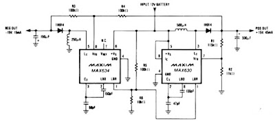
A IC MAX634 inverting regulator is combined with a IC MAX630 to provide a dual tracking approximately 15 Volt output from a 12 Volt DC battery. The reference for the - 15 Volt output is derived from the positive output via R3 and R4. Both regulators are set to maximize output power at low battery voltages by reducing the oscillator frequency , via LBR, when V Batt falls to 8,5 volt. Technical instruction : Max. Input voltage    : 13 Volt / N/a mA Max. Output voltage :-15 Volt , + 15 volt / 45 mA

Simple Mobile Voltage Regulator Circuit Diagram

Image
Build a Simple Mobile Voltage Regulator Circuit Diagram. This simple mobile voltage regulator circuit diagram may save your two meter or CB transceiver if the voltage regulator fails. The 2N3055 should be heat sinked if current drawn by the rig is in excess of 2 A on transmit. This simple mobile voltage regulator circuit diagram will do little under normal operating conditions, but could save expensive equipment if the vehicle`s electrical system loses regulation. Simple mobile voltage regulator circuit diagram

Battery Charger using LM317 Regulator

Image
Battery Charger using LM317 Regulator This Battery Charger is very similar to the universal charger that uses the constant current load. But this is much simpler to build and can be built using only two parties, the LM317 regulator and resistance. The use of diode D is for protection against short circuits. Capacitors C1 and C2 is good voltage regulation. Resistance R2 operates a dummy load when the battery is disconnected. The idea of ​​this magazine is the output current is equal to 1.2 V, divided by the value of R1. Part List: LM317 R1 - see the values in table below R2 - 2.2 kilo-ohms 1/4W C1,C2 - 47uF/25V, or any value will do, the higher the better D - 1N4001 or any similar diode at-least 1A rated

1 3V DC to 12 2V DC Regulator Power Supply

Image
Power supply circuit to generate output below were variations between 1.3V DC to 12.2V DC with 1A current. In addition, the power supply circuit is also equipped with over-current protection or shield against belebih flow. Power supply circuit is very simple, but the quality is quite good, made her basiskan regulator IC LM723 is a pretty legendary. Description: R2 to set the output voltage. The maximum current is determined by R3, over-current protection circuit inside the LM723 to detect the voltage on R3, if it reaches 0.65 V, the voltage output will be off her. So the current through R3 can not exceed 0.65 / R3 although output short-circuit in his. C3 and C4 are ceramic capacitors, as much as possible directly soldered to the PCB, this is because the LM723 is prone to oscillation that is not cool. LM723 works with 9.5V input voltage to 40 V DC and the LM723 can generate its own current of 150mA when the output voltage is not more than 6-7V under input voltage. Specifications: Output...

Battery Switch With Low Dropout Regulator Project

Image
In the form of the LT1579 Linear Technology (www.linear-tech.com) has produced a practical battery switch with an integrated low-dropout regulator. In contrast to previous devices no diodes are required. The circuit is available in a 3.3 V version (LT1579CS8-3.3) and in a 5 V version (LT1579CS8-5), both in SO8 SMD packages. There is also an adjustable version and versions in an SO16 package which offer a greater range of control and drive signals. The main battery, whose terminal voltage must be at least 0.4 V higher than the desired output voltage, is connected to pin IN1. The backup battery is connected to pin IN2. The regulated output OUT can deliver a current of up to 300 mA. The LDO regulator part of the IC includes a pass transistor for the main input voltage IN1 and another for the backup battery on IN2.  Battery Switch With Low-Dropout Regulator circuit Diagram The IC will switch over to the backup battery when it detects that the pass transistor for the main voltage input ...

Build a Car Voltage Regulator Circuit Using LM317

Image
The car cigarette lighter socket does not only light cigarettes, but can be utilized as an electrical channel for powering tools to work on the car such as laptops and other electronic devices. The following circuit diagram shows a way of powering a two-way mobile radio using the LM317T voltage regulator. The LM317 T is an adjustable 3-terminal positive voltage regulator that efficiently provides a load current of 1.5 Amps over an output range of 1.2 V and 37 V. With reference to the circuit, it can accept 14 volts without any hassle and the voltage can be controlled easily with the use of a potentiometer, a 3-terminal resister with sliding contact. The whole circuit will contain the following components:  Printed Circuit Board (PCB) Resistor 1 (R1): 270 ohms Resistor 2 (R2): 2K carbon potentiometer Capacitor 1 (C1): 100nF Capacitor 2 (C2): 1uF tantalum LM317T Voltage Regulator Heat Sink DC Power Jacks Green LED: Power Red LED: Over Voltage Zener Diode: over voltage LED switch The ...

Thrifty Voltage Regulator

Image
One of the drawbacks of a three-pin voltage regulator is that the input voltage needs to be 2.5–3 V higher than the output voltage. This makes these integrated regulators unsuitable for battery power supplies. If, for instance, the output voltage is 5 V, a 9 V battery could be discharged to 7.5 V or thereabouts only. On top of this, most of these regulators draw a current of about 2 mA. Special low-drop versions sometimes offer a solution, but they are not ideal either. The regulator described here is rather thriftier: it draws a current of only 300 µA and the difference between its input and output is only 100–200 mV In the circuit diagram, T1 is arranged as a series regulator, which means that the difference between input voltage and output voltage is limited to the transistor’s saturation potential. Therefore, a 9 V battery can be discharged to about 5 V, which is quite an improvement on the situation with an integrated regulator. Diodes D1-D2-D3, or a suitable zener diode (D4), in ...