Posts

Showing posts with the label Basic

Basic Components for a Home Theater

Image
Many people never bother looking into purchasing a home theater through sheer fear of the decisions that may need to be made in the process. Many among these aren’t even sure of exactly which components are included in a home theater or which ones are needed in order to create an effective and entertaining home theater. For this reason, many people simply do not bother going through the process of looking at their options when it comes to these wonderful systems on the market today much less ever bother actually purchasing one. Basic Components for a Home Theater If you are one of the many who has experienced some degree of confusion when it comes to the individual parts and pieces that are included in a home theater system and what they do, hopefully you will gain a better understanding once you’ve finished reading. The first thing to understand is that there are varying degrees when it comes to home theaters. The following components are the makings of a very basic home theater that...

Basic PLC Ladder Programming Examples 17

Image
Basic PLC Ladder Programming Examples 17 Basic PLC Ladder Programming Training Examples for Beginners.  Hi friends here we are starting here a series of Free Training on PLC Ladder Programming training & tutorials.These PLC Ladder Programs are important to get basics of Ladder programs.  PLC Ladder Practice Problem:  When the Start push button is pressed both motors must run After 10 Sec motor 1 Stops Motor 2 continues running for another 5 sec and stops At this point a lamp is switched on. After 10 Seconds Lamp goes off and cycle restarts . If stop switch is operated at any time , the system will continue to the end of the cycle and then stop. Topics Covered in this example is Conditional Contacts  Ladder Program. Number of PLC Inputs Required X0 – START pushbutton to Start Motor X1 – STOP pushbutton to Stop Motor Number of PLC Outputs Required Y0 – Motor 1 Y1 – Motor 2 Y2 – LAMP PLC Ladder Programming: Note: Example is only for training purposes. No practical i...

Basic Dual Polarity Power Supply

Image
This is a very basic dual polarity power supply circuit diagram, it also called symmetrical power supply or split power supply. It just need the following components: A Center Tapped Transformer Diode rectifier 4 units (or diode bridge 1 unit) Electrolityc capacitor 4 units The value of each component are depending on your needs. For example, if you need dual polarity power supply to supply an 100W amplifier circuit which need 32V voltage supply, then the recommendation are as follow: Transformer: 3A center tapped transformer 24V – 0 – 24V. Diode rectifier 1N5402 : 4 units Electrolityc capacitor (elco) 4700uF/50V – 6800uF/50V : 4 units With above component’s value, the power supply will be able to handle 100W output load. Circuit note: Based on above scheme, the ground is connected to the “E” mark. The “E” is the center of the transformer. In center tap transformer, there are some outputs that have same values (24V for example) and an output which has 0 output. The ground (E) shou...

Basic PLC Ladder Programming Examples 19

Image
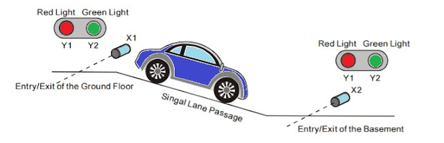
Basic PLC Ladder Programming Examples 19 Basic PLC Ladder Programming Training Examples for Beginners.  Hi friends, here we are starting unique a series of Free Training on PLC Ladder Programming & tutorials. These PLC Ladder Programs are important to learn basics of Ladder programs.   PLC Ladder Practice Problem:  Entry/Exit Control of the Underground Car Park. ·        The entry/exit of the underground car park is a single lane passage which needs the traffic lights to control the cars. Red lights prohibit cars entering or leaving while green lights allow cars to enter or leave. ·        When a car enters the passage from the entry of the ground floor, the red lights both on the ground floor and the basement will be ON, and the green lights will be OFF. Any car entering or leaving is prohibited during the process till the car passes through the passage completely. When the passage is clear...

Basic Functionality

A functional requirement usually has corresponding behavioral and performance condition Functional requirements can always be modelled

Basic LED Glowing Circuit

Image
Components Required: 1) Breadboard 2) 1N4007 Diode 3) 470 ohm resistor 4) LED (Any Color) 5) 9Volt Battery 6) Digital Multimeter Procedure: Connect the 1N4007 diode, 470 Ω resistor & an LED in series in the breadboard.  Connect the 9V battery's positive end to the anode of 1N4007 diode and negative end to the cathode of the LED as shown in the circuit diagram below. Measure the voltage across various points of the circuit using a digital multimeter. Circuit Diagram: Figure 1: Basic LED glowing Circuit simulation made in Multisim Figure 2: Basic LED glowing Circuit