Posts

Showing posts with the label Op

OP AMP INTEGRATOR CIRCUIT DESIGN AND WORKING

The OP AMP Integrator , is a circuit which performs the integration of an input signal. The output of an integrator will be the mathematical integral value of continuous input signal. Such a circuit is obtained by using a basic inverting amplifier configuration if the feedback resistor Rf is replaced by a capacitor Cf. V o = -1/R 1 C F  ∫ 0 T (Vin dt + C) The above equation shows that the output voltage is directly proportional to the negative integral of input voltage and inversely proportional to the time constant R1Cf. Read More.....

Definition of Ideal Op Ampand its Characteristics

Image
Operational Amplifier The operational amplifier is a basic analog building block common to a number of electronic functions performed in instrumentation, computation and control. Op-amp is basically a differential amplifier whose function is to amplify the difference between two input signals. Op-amp is available in IC form. Ideal Op Amp Characteristics The ideal operational amplifier is shown in the below fig, and its equivalent circuit. A signal appearing at the negative terminal V 1 is inverted at the output, a signal at the positive terminal V 2 appears at the output with no change in sign.  Hence the negative terminal is called the “inverting terminal” and the positive terminal the “non-inverting terminal.” In general the output voltage is directly proportional to the difference of the input voltage. The constant of proportionality, - A; is the voltage gain of the amplifier. (a) Symbol            (b) Equivalent Circuit Characteristics The ideal op...

Subwoofer Lowpass Filter using uA741 Single Op Amp Ic Project

Image
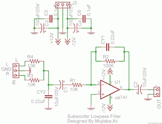
This is the simplest Sub woofer Low Pass filter Circuit using uA741 single op amp ic . The circuit is very low cost with respect to their work. The cut off frequency of this circuit is 25Hz to 80Hz maximum. Using this circuit , you can easily design a 2.1 Sub-woofer Speaker System at your own Home. The circuit contains very few components.In Pakistan, the cost of this circuit with PCB is Rs:45 The same circuit is working in my own hand made sub-woofer system. Parts List:   R1,R3,R4 = 10K 1/4W R2=100K 1/4W CY1,CY2 = 0.22uF Polyester C1,C2 = 10uF/25V Electrolytic IC1 = uA741A Single Op-Amp Ic + 8 Pin Ic Socket 3 Pin Male & Female Connector x 2 2 Pin Male & Female Connector x 1 PCB as in required size 4.5 cm x 3.4 cm

Simple Subwoofer Lowpass Filter using uA741 Single Op Amp Ic

Image
This is the simplest Sub woofer Low Pass filter Circuit using uA741 single op amp ic.The circuit is very low cost with respect to their work. The cut off frequency of this circuit is 25Hz to 80Hz maximum. Using this circuit , you can easily design a 2.1 Sub-woofer Speaker System at your own Home. The circuit contains very few components.In Pakistan, the cost of this circuit with PCB is Rs:45. The same circuit is working in my own hand made sub-woofer system.So Try this  Sub-woofer Low-pass Filter using uA741 Single Op-Amp Ic  Circuit Diagram Parts List: R1,R3,R4 = 10K 1/4W R2=100K 1/4W CY1,CY2 = 0.22uF Polyester C1,C2 = 10uF/25V Electrolytic IC1 = uA741A Single Op-Amp Ic + 8 Pin Ic Socket 3 Pin Male & Female Connector x 2 2 Pin Male & Female Connector x 1 PCB as in required size 4.5 cm x 3.4 cm