Posts

Showing posts with the label microphone

Build a 9V Wireless Microphone FM Transmitter

Image
This FM transmitter circuit can be used as a wireless microphone,  can be received by an ordinary 88- to 108-MHz FM broadcast receiver. For the power supply, this transmitter circuit is powered by a 9 V battery. To comply with the radiation limit of FCC rules, keep the antenna length under 12 inches. L1 is 6 turns of #24 wire wound around a pencil or a 1/4″ form, with turns spacing of 1 wire diameter. C6 is a gimmick capacitor which has value about 1 pF.  9V Wireless Microphone FM Transmitter Circuit Diagram
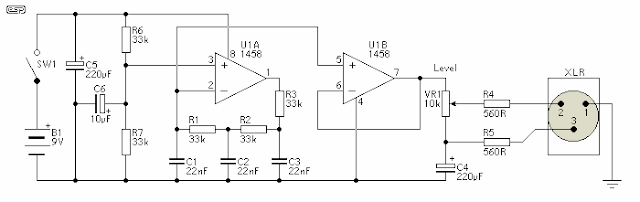
Microphone Circuit Test Oscillator Diagram

Image
Description This unit would be mounted in a small plastic or preferably metal box, with a 9V battery, level control, a male XLR connector (same as on a mic) and a switch.  Current drain is low, since the circuit only uses one dual opamp.  There is no need for a high quality device, and a 1458 is all that is needed. Circuit Diagram The first stage is the oscillator itself.  This is a simple three stage phase shift oscillator - a circuit that is remarkably uncommon - which is to say I have never seen it used elsewhere.  I designed it for another project a few years ago, and I don't understand why it is not more common. If you want to tune it, you can use a 50k pot instead of R1.  I suggest that if tuned, set it to A-440 Hz.  Frequency stability is not wonderful, and it changes by a few Hertz as the battery discharges, but this is unlikely to cause problems - it is a test oscillator, not a tuning standard.  As shown, frequency will be about 430Hz, dependi...

Low Noise Microphone preamplifier

Image
This circuit use to raise the gain to reduce noise or amplify the signal. And this circuit use IC OP27 / OP37 , this is precision opertional amplifier ,lower noise , and higher speed with the  same input ofset with drift specifications as the OP07 . Both parts have a 10 uV offset , 0.2 uV drift , and 1.8 million gain. Coupled with low voltage noise of 3.5 nV  at 10 Hz and a low 1 /f noise corner frequency of 2.7 Hz, the  OP27 / OP37 are optimized for accurate amplification of low - level signal.  See schematic and pin configuration below : Click to view Larger Output swing about 10 V into 600 Ohm. Input voltage maximum 25 V. This circuit also can use to , Low noise DC amplifiers , Microphone Amplifiers , Precision Amplifier , Tape - Head  Preamplifiers , Termocouple Amplfiers , Low - level Signal Processing , Medical instrumentation m Strain - gauge Amplifiers , High accuracy Data Acquistion.

Wireless transmitter microphone circuit

Image
Wireless FM transmitter circuit Microphone Hi Fi using a model-ready transmitters, this is because the buil-up transmitter module has a transmission capability of a stable and very effective to emit 10 mW RF. so that the target of Hi Fi FM Wireless Microphone transmitter circuit Hi Fi can be realized. The series can be seen from the FM transmitter Microphone Wireless Hi Fi transmitter module is that it stands alone with an additional R7, R8 and C6 to produce high-quality RF frequency. In the series of FM transmitter Microphone Wireless Hi Fi module requires power consumption of a battery 12 VDC. Transmission antenna is directly connected with the circuit module Wireless FM transmitter Wireless FM Microphone Hi Fi. Input section of the circuit transmitter Wireless FM Microphone Hi Fi signals to the modulation of 100mV RMS. A microphone preamplifier with IC TL081 is used to reproduce the signal from the microphone into a signal with 100mV rms level as needed this wireless FM transmitter ...