Posts

Showing posts with the label PLC

Basic PLC Ladder Programming Examples 17

Image
Basic PLC Ladder Programming Examples 17 Basic PLC Ladder Programming Training Examples for Beginners.  Hi friends here we are starting here a series of Free Training on PLC Ladder Programming training & tutorials.These PLC Ladder Programs are important to get basics of Ladder programs.  PLC Ladder Practice Problem:  When the Start push button is pressed both motors must run After 10 Sec motor 1 Stops Motor 2 continues running for another 5 sec and stops At this point a lamp is switched on. After 10 Seconds Lamp goes off and cycle restarts . If stop switch is operated at any time , the system will continue to the end of the cycle and then stop. Topics Covered in this example is Conditional Contacts  Ladder Program. Number of PLC Inputs Required X0 – START pushbutton to Start Motor X1 – STOP pushbutton to Stop Motor Number of PLC Outputs Required Y0 – Motor 1 Y1 – Motor 2 Y2 – LAMP PLC Ladder Programming: Note: Example is only for training purposes. No practical i...

Push to ON PUSH to OFF PLC program using NO NC and Coil

Image
This is  Interview question that every PLC programmer came across in his carrier.The Question is very tricky and shows the fundamentals (basic Ladder Laws) and depth of candidates knowledge. Today we are going to discuss PLC program for Push to ON device  and Push to Off Device.But the trick is that we have to use  only Normally open(NO) ,Normally Close (NC) contacts ,and Coil as output only(No timer,Counter, OSR ). In short there will be a single Push Button Input (X0) , and one Output (Y0). When user press Push button for 1st time output will be ON ,when user Presses Push Button for 2nd time output will be OFF. This is also called as "Push to On Push to Off " logic.Analogy can be provided with "TV" on and off Push Button.    We Can Break Sequence Like This : 1) Push Button Pressed (X0) ==> Output (Y0)On 2)Push Button Released (X0)==> Output (Y0) Latched 3)Push Button Pressed (X0)==> Output (Y0 )Off 4)Push Button Released (X0)==> Output (Y0) O...

HOW PLC SCAN CYCLE WORKS

Image
HOW PLC SCAN CYCLE WORKS? Hi Friends … Greetings , Today want to share with you how PLC actually works. PLC’s work on the principal on SCAN CYCLE. Lets find out how PLC Work? It works in Following Stages. STAGE 1.Regenerate input signal   Before the execution of the program, PLC reads the On/Off status of the external input signals into the input signal memory at a time.    The On/Off status of the input signal during the execution of the program will not change the signal status in the input signal memory. The new On/Off status will be read in the next scan.   There will be approximately a 10ms delay from the On→Off or Off→On changes to the status being recognized by the contact in the program. The delay time may be affected by the scan time in the program. STAGE 2.Program processing After the PLC reads the On/Off status of every input signal in the input signal memory, it will start to execute every instruction in the program in order starting from address 0. The e...

Basic PLC Ladder Programming Examples 19

Image
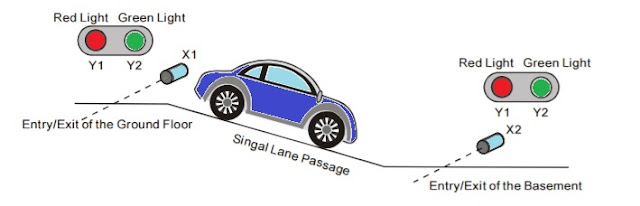
Basic PLC Ladder Programming Examples 19 Basic PLC Ladder Programming Training Examples for Beginners.  Hi friends, here we are starting unique a series of Free Training on PLC Ladder Programming & tutorials. These PLC Ladder Programs are important to learn basics of Ladder programs.   PLC Ladder Practice Problem:  Entry/Exit Control of the Underground Car Park. ·        The entry/exit of the underground car park is a single lane passage which needs the traffic lights to control the cars. Red lights prohibit cars entering or leaving while green lights allow cars to enter or leave. ·        When a car enters the passage from the entry of the ground floor, the red lights both on the ground floor and the basement will be ON, and the green lights will be OFF. Any car entering or leaving is prohibited during the process till the car passes through the passage completely. When the passage is clear...