Posts

Showing posts from April, 2017

Build Improvised Fan Grills

Image
Making your own grill for your fans would be a lot easier and cheaper. You could use all materials that can be found in your home. Your main component would be your old fan, removed its metal ring and you can now measure the desired length or size of grid that you will be needed. Cut the grid across so it will be easier to cut, then place it in the tower and use the same screw you removed in the fan. Now you can put the grid holding fan back in its place. Clean up and you can now use your very own fan grills that cost almost nothing but your patience.
High Voltage regulator schematics

Image
In this series of essentially the same principle with the power supply, but power supply is working to produce high voltage. And high voltage which is regulated by this series becomes more filtered and either used for electronic devices that are not easily damaged. High Voltage regulator schematics Component List R1_____________1K R2_____________470K R3_____________330K R4_____________20K C1_____________39uF 450V C2_____________39uF 450V C3_____________39uF 450V C4_____________39uF 450V C5_____________10uF 25V C6_____________220nF 250V C7_____________100nF 400V D1_____________1N4007 D2_____________1N4007 D3_____________1N4007 D4_____________1N4007 D5_____________1N4148 D6_____________1N4148 TR1____________MJE13005 TR2____________MPSA92 TR3____________MPSA42

Ego WiFi HD Action Camera

Image
Your friends might laugh at you wholeheartedly when they see you sporting something that looks like a walnut on your head – the £159.99 Ego WiFi HD Action Camera which will come in black, blue, red, white or yellow colors, but they certainly will not laugh any more when they check out the kind of daredevil stunts that you perform, recording all of it from a vantage point of view to show them just how much cojones you have over the rest of your clique. The Ego WiFi HD Action Camera will basically capture all of your action and adventure in 1080p high definition, and if you happen to own a smartphone or compatible tablet, live video footage can also be streamed onto your screen thanks to the integrated Wi-Fi chip on the Ego WiFi HD Action Camera. There is a built-in microphone that will perform all the recording of the slew of high pitch squeals and applause amidst the audience who are watching your every daredevil move that drips with adrenaline and courage. Not only that, the Ego WiFi

Introduction to Amplifier

Image
Amplification is the method of increasing the amplitude of a AC signal current or voltage such as audio signal for sound or video signal for a television picture. The amplifier allows a small input signal to control a bigger amount of power in the output circuit. The output signal is a replica of the original input signal but has higher amplitude. Amplification is necessary as in most applications, the signal is weak to be used directly. For example, an audio output of 1mV from a microphone is unable to drive a loud speaker which requires a few volts to operate. Hence, the signal require to be amplified to a few volts before it can be fed in to the loud speaker. NP N Transistor Circuit Configurations An example of different type of transistor configurations in the circuit is as shown in Figure one below. (1) The common emitter(CE) circuit makes use of emitter as its common electrode. The input signal is applied to the base and the amplified output is taken from the collector. This is t

OP AMP INTEGRATOR CIRCUIT DESIGN AND WORKING

The OP AMP Integrator , is a circuit which performs the integration of an input signal. The output of an integrator will be the mathematical integral value of continuous input signal. Such a circuit is obtained by using a basic inverting amplifier configuration if the feedback resistor Rf is replaced by a capacitor Cf. V o = -1/R 1 C F  ∫ 0 T (Vin dt + C) The above equation shows that the output voltage is directly proportional to the negative integral of input voltage and inversely proportional to the time constant R1Cf. Read More.....

Bridge Rectifier LED Indicator

Image
Using a few diodes and a LED, you can make a nice indicator as shown in associated schematic diagram that can be used for a lot of applications (with a bit of luck). It’s quite suitable for use in series with a doorbell or thermostat (but don’t try to use it with an electronically con-trolled central-heating boiler!). This approach allows you to make an attractive indicator for just a few pennies.     The AC or DC current through the circuit causes a voltage drop across the diodes that is just enough to light the LED. As the voltage is a bit on the low side, old-fashioned red LEDs are the most suitable for this purpose. Yellow and green LEDs require a somewhat higher forward voltage, so you’ll have to first check whether it works with them. Blue and white LEDs are not suitable. You also don’t have to use modern high-efficiency types (sometimes called ‘2-mA LEDs’ or ‘3-mA LEDs’). If a DC current flows through the circuit and the LED doesn’t light up, reverse the plus and minus lead

Bipolar Transistor Tester

Image
This tester is primarily meant to test bipolar transistors. It can indicate the type of the transistor as well as identify its base, collector and emitter pins. The circuit is very simple. The direction of current flow from the terminals of the transistor under test (TUT) is indicated by a pair of LEDs (green-red). An npn transistor produces a red-green-red glow, while a pnp transistor produces a green-red-green glow, depending on the test point that connects to the terminal of the transistor. Emitter and collector are differentiated by pressing pushbutton switch S1 that actually increases the supply voltage of the circuit by about 5.1V. At the heart of the circuit is IC CD4069 (IC3), which oscillates and produces pulses required to test a pair of transistor leads for conduction in both the directions. Different combinations are selected by an arrangement of counter CD4040 (IC1) and bilateral switch CD4016 (IC2). Fig. 1 shows the circuit of the bipolar transistor tester. A pair of LEDs

LEDs IN SERIES PARALLEL

Image
LEDs IN SERIES LEDs can be placed in series providing some features are taken into account. The main item to include is a current-limiting resistor. A LED and resistor is called a string. A string can have 1, 2, 3 or more LEDs. Three things must be observed: 1. MAXIMUM CURRENT through each string = 25mA. 2. The CHARACTERISTIC VOLTAGE-DROP must be known so the correct number of LEDs are used in any string. 3. A DROPPER RESISTOR must be included for each string. The following diagrams show examples of 1-string, 2-strings and 3-strings: LEDs IN PARALLEL LEDs CANNOT be placed in parallel - until you read this: LEDs "generate" or "possess" or "create" a voltage across them called the CHARACTERISTIC VOLTAGE-DROP  (when they are correctly placed in a circuit). This voltage is generated by the type of crystal and is different for each colour as well as the "quality" of the LED (such as high-bright, ultra high-bright etc). This characteris

Simple LT3582 12 DC 5V to 12V DC Converter

Image
Using LT3582-12 dual channel DC DC converter integrated circuit, manufactured by Linear Technology, can be designed a very simple step up dc converter. This 5 to 12V c converter electronic project provide both positive and negative outputs required in many biasing applications such as active matrix OLED (organic light-emitting diode)displays as well as CCD (charge coupled device) applications. Simple LT3582-12 DC 5V to 12V DC Converter  Circuit Diagram

5 Watt Class A Audio Amplifier Circuit Diagram

Image
This solid-state push-pull single-ended Class A circuit is capable of providing a sound comparable to those valve amplifiers, delivering more output power (6.9W measured across a 8 Ohm loudspeaker cabinet load), less THD, higher input sensitivity and better linearity. Voltage and current required for this circuit are 24V and 700mA respectively, compared to 250V HT rail and 1A @ 6.3V filament heating for valve-operated amplifiers. The only penalty for the transistor operated circuit is the necessity of using a rather large Heatsink for Q2 and Q3 (compared to the maximum power delivered).In any case, the amount of heat generated by this circuit can be comparable to that of a one-valve amplifier. An optional bass-boost facility can be added, by means of R5 and C5.   Circuit diagram: Parts: P1 = 47K R1 = 100K R2 = 12K R3 = 47K R4 = 8.2K R5 = 1.5K R6 = 2.7K R7 = 100R R8 = 100R R9 = 560R-1/2W R10 = 1R-1/2W Q1 = BC560 Q2 = BD439 Q3 = BD439 C1 = 10uF-63V C2 = 10uF-63V C3 = 47uF-25V C4 = 100uF-

3A Power supply for USB devices

Image
This is 5V 3A power supply to drive two USB based devices simultaneously. This power supply is design around LM2576-5.0 switching regulator IC and the main reasons to choose this IC is its low parts count, small heat sink requirements and its inbuilt current limit protection feature. We specially design this power supply to work with development boards / single board computer (SBC) platforms such as Raspberry Pi, Banana Pi, BeagleBone, etc. This power supply can also be used to provide power to USB OTG peripherals over USB Y cables. We test this setup and got successful results with Huawei Ascend P6 mobile phone. [ ]

0 24VDC Digital PIC Power Supply

Image
This is 0-24VDC digital PIC power supply circuit. This variable power supply controlled with PIC microcontroller. There is LCD display in this circuit which will show the actual value of power supply output. This power supply use push on switch to adjust the output voltage and current value. Schematic Diagram: Component List : C1 = 2000uF per AMP, 40V (adjust capacity to power supply amps) C2,C3,C12,C15,C18,C21 = 0.1uF CER C4 = 0.01uF CER C5A,C5B,C5C,C5D = 0.01uF CER C6,C7 = 0.05uF CER C8 = Not used C9,C11,C19,C20 = 1uF CER C10 = 470uF 15V EL RADIAL C13 = 4.7µF 50V EL RADIAL C14 = 0.001uF CER C16,C17 = 22pF CER D1,D2,D4,D5 = 1N4148 D3 = 1N4004 Br1 = 1<10A BRIDGE RECTIFIER (adjust seize to power supply amps) DZ1 = 1N4751 30V ZENER IC1 = LM317KCS TO220 IC2 = LM337LZ TO92 IC3 = LT1491CN special HV opamp, do not substitute IC4 = PIC16F876A Q1 = 2N3906 Q2A to Q2D = TIP142TU 1 to 5 transistors (adjust quantity to power supply amps) Q3A to Q3D = 2N3904 (adjust quantity to power supply am

Low Cost Stereo Level Indicator Circuit Diagram

Image
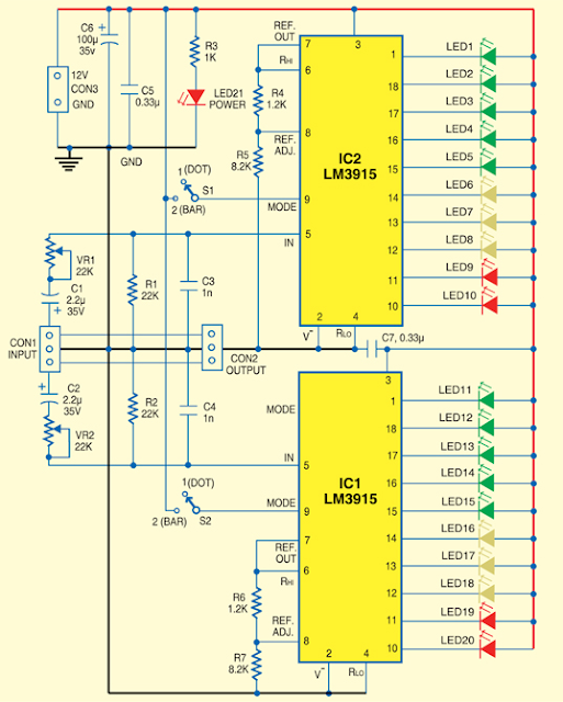
Usually, Low-Cost Stereo Level Indicator home stereo power amplifiers don’t have output level indicators . An output power level indicator can be added to each channel of these stereo power amplifiers . As low levels of the output power are not disturbing and damaging to the people, there is no need to add a preamplifier and low-level detector before IC LM3915. But you should know when the output power becomes considerably high. Here we present a very simple, low-cost stereo-level indicator circuit for home power amplifiers with power rating of around 0.5W. The circuit is built around two LM3915 dot/bar display driver ICs (IC1 and IC2). LM3915 senses analogue voltage levels to drive ten LEDs, providing a logarithmic 3dB/step analogue display. Stereo Level Indicator Circuit Diagram The voltage levels below 1V are not important because these correspond to a low level of the audio signal. Similarly, input voltage levels above 30V correspond to too high levels of the output power, which

USB Switch Schematic Circuit

Image
Anyone experimenting or developing USB ported peripheral hardware soon be comes irritated by the need to disconnect and connect the plug  in order to reestablish communication with the PC. This process is necessary for example each time the peripheral equipment is reset or a new version of the firmware is installed. As well as tiresome it eventually leads to excessive contact wear in the USB connector. The answer is to build this electronic isolator which disconnects the peripheral device at the touch of a button. This is guaranteed to reduce any physical wear and tear and restore calm once again to the workplace. Circuit image :   USB Switch Schematic Circuit Image The circuit uses a quad analogue switch type 74HC4066. Two of the switches in the package are used to isolate the data path. The remaining two are used in a classic bistable flip-flop configuration which is normally built using transistors. A power MOSFET switches the power supply current to the USB device.  Capacitor

Pyro Electric Fire Alarm

Image
Here is an ultra-sensitive fire sensor that exploits the direct piezoelectric property of an ordinary piezo element to detect fire. The lead zircon ate titan ate crystals in the piezo element have the property to deform and generate an electric gate protected p-channel MOSFETs in the inputs. It has high speed of performance and low input current requirements.There are two inputs—the non-inverting input (pin 3) connected to the piezo element through diode D7 (OA71) that carries the voltage signal from the piezo element and the inverting input (pin 2) that gets a preset voltage momentarily changes the voltage level at pin 3 of IC1 and its output swings high. Transistor T1 conducts taking the reset pin 12 of IC2 to ground. IC2 is now enabled and starts oscillating. With the shown values of the oscillating components C3 (0.22μ) and R6 potential when heated, thus converting the piezo element into a heat sensor. The circuit described here is very sensitive. It gives a warning alarm if

Temperature Monitor Circuit Diagram

Image
A simple op-amp circuit that will trigger a relay when a preset temperature is reached. Please note that there is no hysteresis in this circuit, so that if the temperature changes rapidly, then the relay may switch rapidly. Temperature Monitor Circuit Diagram Circuit Notes : This circuit uses an ordinary NTC thermistor with a resistance of 47k at room temperature. A suitable part from Maplin Electronics is FX42V. The circuit is set in balance by adjusting the the 47k potentiometer. Any change in temperature will alter the balance of the circuit, the output of the op-amp will change and energize the relay. Swapping the position of the thermistor and 47k resistor makes a cold or frost alarm. Calibration : At room temperature (25 degrees Celsius) a 47k NTC thermistor resistance is approximately 47k. The non-inverting op-amp input will then be roughly half the supply voltage, adjusting the 47k pot should allow the relay to close or remain open. To calibrate the device, the thermistor idea

Making an RIAA phono preamp

Image
Before we start today's blog post, I think I really need to clarify what we’re discussing. I’ve recently got back into vinyl in a big way. Part of the reason for this is the fantastic “Vinyl Decision” in Taipei, run by a couple of very fine gentlemen by the names of Mark and Terry ( https://www.facebook.com/VinylDecision / http://www.vinyldecision.com/ ). If you're in Taipei, and like music, pay them a visit. A recent purchase from there brought back memories of trying again, and again (and again) to play guitar like my guitar heroes as a teenager in the 1980s. In fact, vinyl is making quite a comeback worldwide. A lot of people are realizing that digital versions just lack some of the personality that vinyl can provide. Many of them are buying old record players/turntables and wiring them up to their modern amps. However, they are often disappointed to find that the output audio is very quiet and lacking bass. This is because records are/were recorded using a very specific f

Simple Low Distortion Audio Amplifier Circuit Diagram

Image
This is the Simple Low Distortion Audio Amplifier Circuit Diagram. The circuit was designed and sold as a card by a purveyor of surplus components but, even using mostly manufacturer's rejected transistors, we managed to get about 0.02% total harmonic distortion at 30 watts with a ±25v power supply into 8 ohms.: no bad figure even in these days of MOSFET and ICs. In 1977 anything below 0.1% was considered excellent. And this figure was pretty repeatable without doing much selection.  The problem of course is that since I haven't touched this amplifier for many a year I have absolutely no idea what modern transistor types one should use for it but they are not critical: output transistors and drivers need to be the correct type but the other transistors can be small signal types - as long as they can handle the full voltage between + and - supplies.  Simple Low Distortion Audio Amplifier Circuit Diagram   Tr1 and Tr2 are a long-tailed pair (LTP to save typing). It is quite commo

Mobile Phone Travel Charger Circuit Diagram

Image
This is a Mobile Phone Travel Charger Circuit Diagram. At this point is an ideal cellular phone charger using 1.5 Volt ballpoint cells to charge mobile phone while wandering. It can refill cell phone battery three before four period in the field of spaces everyplace AC power is not on hand. A good number of the cell phone phone batteries are rated by the side of 3.6 in opposition to/500 mA. A single create torch cell can provide 1.5 volts and 1.5 Amps current. So if four pen cells are connected serially, it wish form a battery bunch with 6 volt and 1.5 Amps current. while power is practical to the circuit through S1, transistor T1 conducts and grassy LED light. Mobile Phone Travel Charger Circuit Diagram What time T1 conducts T2 furthermore conducts since its dishonorable becomes denial. Charging current flows from the satellite dish of T1. To reduce the charging voltage to 4.7 volts, Zener diode ZD is used. The output gives 20 mA current on behalf of stupid charging. If additio

Capacitance and Uses of Capacitors

Image
unpolarised capacitor symbol   polarised capacitor symbol Capacitance Capacitance (symbol C) is a measure of a capacitor's ability to   store charge . A large capacitance means that more charge can be stored. Capacitance is measured in farads, symbol F. However 1F is very large, so prefixes (multipliers) are used to show the smaller values: µ (micro) means 10 -6  (millionth), so 1000000µF = 1F n (nano) means 10 -9  (thousand-millionth), so 1000nF = 1µF p (pico) means 10 -12  (million-millionth), so 1000pF = 1nF Charge and Energy Stored The amount of charge (symbol Q) stored by a capacitor is given by: Charge,    Q = C × V   where: Q = charge in coulombs (C) C = capacitance in farads (F) V = voltage in volts (V) When they store charge, capacitors are also storing energy: Energy,    E = ½QV = ½CV²     where  E = energy in joules (J). Note that capacitors return their stored energy to the circuit. They do not 'use up' electrical energy by converting it to heat as a resistor do