Making an RIAA phono preamp

Before we start today's blog post, I think I really need to clarify what we’re discussing. I’ve recently got back into vinyl in a big way. Part of the reason for this is the fantastic “Vinyl Decision” in Taipei, run by a couple of very fine gentlemen by the names of Mark and Terry (https://www.facebook.com/VinylDecision / http://www.vinyldecision.com/). If you're in Taipei, and like music, pay them a visit. A recent purchase from there brought back memories of trying again, and again (and again) to play guitar like my guitar heroes as a teenager in the 1980s.
In fact, vinyl is making quite a comeback worldwide. A lot of people are realizing that digital versions just lack some of the personality that vinyl can provide. Many of them are buying old record players/turntables and wiring them up to their modern amps. However, they are often disappointed to find that the output audio is very quiet and lacking bass. This is because records are/were recorded using a very specific frequency response. The output of a record player is much lower than “line level”, but it is also much heavier on the treble and lighter on the bass. This frequency curve is what is known as the RIAA (Recording Industry Association of America) equalization curve. This was necessary primarily because heavy bass would have the needle jumping around too much on the record, affecting sound quality, and, I’d imagine, increasing wear and tear. Additionally it allowed the grooves to be thinner, hence allowing more grooves (and therefore longer playing time) per record.
The RIAA Equalisation Curve:

Older amps had a specific input labelled “phono”, which specifically catered to record players. This input would be wired to a built-in preamp which would not only amplify the signal to line level, but would also correct the frequency curve, hence enabling the amp to output the sound as it was originally intended. Many newer amplifiers do not have a phono input and therefore an external preamp is required between the record player and the amp to enable the use of one of the line-level inputs.
And that’s where today’s project comes in. We’re going to make an RIAA/phono preamp.
There are many, many preamp schematics out there—some simple, and some insanely complex. I wanted to find one which was relatively simple, while still accurately correcting the RIAA recording frequency curve. I finally settled on this one: http://phonoclone.com/diy-pho5.html (“The Very Simple Phono Stage”). I highly recommend you go to that page and read through it if you decide to tackle this project. It’s very well explained and highly educational.

Rather than build a power supply, I decided to buy a 30V DC one ready-made, and then split it so that it would have +15V, OV and -15V. To do that, I made a simple voltage splitter like so:


Additionally, I added a diode right where the 30V meets the board to protect the circuit in case anyone ever plugs the power supply in the wrong way around.
I also decided to add some small 100nF capacitors at the +15V and -15V legs of the chips to reduce any picked up noise to a minimum.
OK, let's get going. We're going to need an enclosure. Here’s the box I’m going to use with my markings for where to put the connectors:

From left to right, it’s going to have a grounding connector (which may or may not be needed depending on whether there is a humming noise – note that the humming noise can sometimes be removed by unplugging your record player, turning the plug around and then plugging it back in [assuming it’s symmetrical]), left output RCA jack, right output RCA jack, left input RCA jack, right input RCA jack, and finally the power input (30V DC negative sleeve [it is imperative that the 0V from the power supply is electrically isolated from the enclosure, so don’t be using any metal connectors that might join them]).
Here it is with the holes drilled and the connectors, erm, connected:

It’s a good idea to test stuff like this out on breadboard before you switch your soldering iron on. Here’s an early version of mine:

Once the circuit design is more or less finalized, it’s time to lay it out for veroboard, like so. Yes, this is how I do it:

And just for you, here it is done properly on the computer. You may notice a few small changes between the initial pencil sketch and the final layout. As with all images, you can click to enlarge.

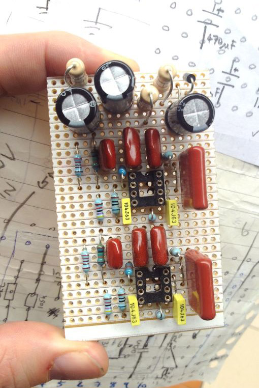
Here we have the components mounted on the board:

Now it’s time to think about mounting the board in the box. It’s pretty important to secure the board in such a way that it doesn’t move around and touch something it shouldn’t. You can see here that I’ve drilled a couple of holes through the board:

Now we drill a couple of holes in the enclosure that match up with the hole positions on the board. I’ll eventually use plastic mounts to hold the board securely in place.


Before placing the board in the box, we add the wires (apologies for the overexposed photo):

Now that the board’s in place, we can connect the wires to the connectors, like so:

Once we're happy that the circuit’s done, we secure the connectors in place with thread lock:

Here's how it looks after that:

Finally, a little bit of the old in and out so we don’t mix up the cables:

And we're done. I'm happy to be able to verify that “The Very Simple Phono Stage” sounds fantastic.


Comments
Post a Comment