Posts

Showing posts with the label Oscillator

Comparator Based Crystal Oscillator Circuit Diagram

Image
Although a simple crystal oscillator may be built from one comparator of an LT1720/LT1721, this will suffer from a number of inherent shortcomings and design problems. Although the LT1720/LT1721 will give the correct logic output when one input is outside the common mode range, additional delays may occur when it is so operated, opening the possibility of spurious operating modes. Therefore, the DC bias voltages at the inputs have to be set near the center of the LT1720/LT1721’s common mode range and a resistor is required to attenuate the feedback to the non-inverting input. Unfortunately, although the output duty cycle for this circuit is roughly 50%, it is affected by resistor tolerances and, to a lesser extent, by comparator offsets and timings. Comparator Based Crystal Oscillator Circuit Diagram If a 50% duty cycle is required, the circuit shown here creates a pair of complementary outputs with a forced 50% duty cycle. Crystals are narrow-band elements, so the feedback to the non...
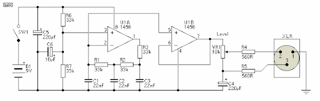
Microphone Circuit Test Oscillator Diagram

Image
Description This unit would be mounted in a small plastic or preferably metal box, with a 9V battery, level control, a male XLR connector (same as on a mic) and a switch.  Current drain is low, since the circuit only uses one dual opamp.  There is no need for a high quality device, and a 1458 is all that is needed. Circuit Diagram The first stage is the oscillator itself.  This is a simple three stage phase shift oscillator - a circuit that is remarkably uncommon - which is to say I have never seen it used elsewhere.  I designed it for another project a few years ago, and I don't understand why it is not more common. If you want to tune it, you can use a 50k pot instead of R1.  I suggest that if tuned, set it to A-440 Hz.  Frequency stability is not wonderful, and it changes by a few Hertz as the battery discharges, but this is unlikely to cause problems - it is a test oscillator, not a tuning standard.  As shown, frequency will be about 430Hz, dependi...

Sawtooth to Triangle Converter for Oscillator Circuit

Image
This wave shaper needs an input saw that goes from Vss to (ideally) Vdd. It works well with the 4069 VCO designed by René Schmitz. Any saw will work as long as the wave is centered halfway between the rails. It works as follows: The upper set of 2 linear mode gates provide an inverted and noninverted copy of the saw. The 3 logic gates at the bottom provide a sort of comparator that switches at halfway between the rails.   Sawtooth to Triangle Converter for Oscillator Circuit Diagram The 4007 provides 2 P-MOSFETs that alternately select the inverted or noninverted saw signal depending on where the saw is in it's cycle. This causes the ramp to reverse directions every half cycle. Any imperfection in the saw will show up in the resulting output. The linear mode gate furthest to the right provides soft clipping that turns the triangle wave into something like a sine wave. It sounds like it has fewer harmonics than the triangle. To use with FatMan sawtooth output: Power all IC...

Voltage Controlled Oscillator

Image
In most cases, the frequency of an oscillator is determined by the time constant RC. However, in cases or applications such as FM, tone generators, and frequency-shift keying (FSK), the frequency is to be controlled by means of an input voltage, called the control voltage. This can be achieved in a voltage-controlled oscillator (VCO). A VCO is a circuit that provides an oscillating output signal (typically of square-wave or triangular waveform) whose frequency can be adjusted over a range by a dc voltage. Voltage Controlled Oscillator Block Diagram : An example of a VCO is the 566 IC unit, that provides simultaneously the square-wave and triangular-wave outputs as a function of input voltage. The frequency of oscillation is set by an external resistor R1 and a capacitor C1 and the voltage Vc applied to the control terminals. Figure shows that the 566 IC unit contains current sources to charge and discharge an external capacitor Cv at a rate set by an external resistor R1 and the mo...

Project of Overtone Crystal Oscillator Circuit Diagram

Image
Build a simple Project of Overtone Crystal Oscillator Circuit Diagram. A crystal oscillator is an electronic oscillator circuit that uses the mechanical resonance of a vibrating crystal of piezoelectric material to create an electrical signal with a very precise frequency.   Overtone Crystal Oscillator Circuit Diagram This frequency is commonly used to keep track of time (as in quartz wristwatches), to provide a stable clock signal for digital integrated circuits, and to stabilize frequencies for radio transmitters and receivers. The most common type of piezoelectric resonator used is the quartz crystal, so oscillator circuits incorporating them became known as crystal oscillator s, but other piezoelectric materials including polycrystalline ceramics are used in similar circuits..  This oscillator is designed for overtone crystals in the 20-100 MHz range operating in the third and fifth mode. Operating frequency is determined by the tuned circuit.

Crystal Controlled Reflection Oscillator Circuit Diagram

Image
How to build a Crystal-controlled-reflection-oscillator circuit diagram . This is a simple crystal controlled reflection oscillator circuit, this unit is easily tunable and stable, consumes little power, and costs less than other types of oscillators tlmt operate at the same frequencies. This unusual combination of features is made possible by a design concept that includes operation of the transistor well beyond the 3 dB frequency of its current-versus- frequency curve.   Crystal Controlled Reflection Oscillator Circuit Diagram The concept takes advantage of newly available crystals that resonate at frequencies up to about 1 GHz.The emitter of transistor Q is connected with variable capacitor Cl and series-resonant crystal X. The emitter is also connected to ground through bias resistor Rl. The base is connected to the parallel combination of inductor L and capacitor C3 through DE-blocking capacitor and C4 and is forward biased with respect to the emitter by resistors R3 and...

Simple Audio oscillator

Image
It is a very simple build a simple Audio-oscillator Circuit Diagram  Project. The circuit`s frequency of oscillation is/= 2.8/ [C1 x (R1 + R2)]. Using the values shown, the output frequency can be varied from 60 Hz to 20 kHz by rotating potentiometer R2. A portion of IC1`s output voltage is fed to its noninverting input at pin 3. Audio Oscillator Circuit Diagram: The voltage serves as a reference for capacitor Cl, which is connected to the noninverting input at pin 2 of the IC. That capacitor continually charges and discharges around the reference voltage, and the result is a squarewave output. Capacitor C2 decouples the output.

Oscillator Sine wave Circuit Diagram

Image
This circuit is a sine wave oscillator which uses operational amplifiers working in oscillation back (positive feedback), or the oscillation output to the input. This oscillator is called Wien bridge circuit is often used. The oscillator Sine wave oscillator is difficult to be done due to the distortion of the oscillation signal, different oscillator square wave, triangle wave oscillator (sawtooth). Oscillator Sine wave Circuit Diagram In the case of C1 = C2 = C, R = R1 = R2, giving the frequency of oscillation and can be calculated using the following formula. Formula Sine Wave Oscillator The example of the circuit was made this time is shown below. f = 1 / (2 x 3.14 x 10 -6 0.01 x 10 x 15 x 3) f = 1 / (0.942 x 10 -3) f = 1.062 x 10 3 f = 1062 Hz The actual frequency of the circuit was 900 Hz.