Posts

Showing posts with the label to

How to Build Unregulated Linear Power Supply
Image
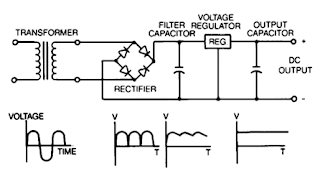
Unregulated power supplies contain four basic components: transformer, rectifier, filter capacitor, and a bleeder resistor. This type of power supply, because of Us simpticity, is the least costly and most reliable for low power requirements. The disadvantage is that the output voltage is not constant It will vary with the input voltage and the load current, and the ripple is not suitable for electronic applications. The ripple can be reduced by changing the filter capacitor to an LC (inductor-capacitor) filter but the cost to make this change would make use of the regulated linear power supply a more economical choice.

Combine stereo input to one output

Image
Here , I will give a circuit of schemes that are used to combine 2 pieces input or stereo to 1 input mono. Why 2 inputs in to one because, if we need a stereo amplifier we want to become a stronger by combining the two input into one input, so that a higher power output. Actually without any circuit above we can combine stereo amplifier into mono, but the sound output less than the maximum , need for this additional combiner circuit. Part List = R1______150K R2______920R R3______150K R4______920R R5______920R U1______NE5532 For balance _: R1 / R2=R3 / R4 For balance _: R1 = R3 Gain ______: R5 / R1 = R5 / R3

How to Test a diode

Image
Hello Everyone ... Today i am going to show you how we test a diode using a digital multimeter.In this article, we will go over different tests that we can use to check whether a diode is good or not, all by utilizing the functions of a digital multimeter. There are many checks we can do to see if a diode is functioning the way it should. We will use and exploit the characteristics and behaviors that a diode should show if it is good and, in thus doing so, determine whether is good or defective.So let's start ... Test of a diode with the ohmmeter of a multimeter :   A very good test you can do is to check a diode with your multimeter set to the ohmmeter setting. This is a simple test we can do to check whether it is good, open, or shorted. So we take the ohmmeter and place it across the leads of the diode. The orientation is very important. Anode-Cathode Diode Resistance Test   We first take the ohmmeter and place the positive probe on the anode of the diode (the black part of...

SP How to Make an AVR Perform Multiple Tasks

Image
This article describes a way to create an AVR perform multiple tasks. Beginners who want to urge an in-depth information in AVR assemble language programming will seek this project. The assembly language helps to utilize all the functions and capabilities of the processor. browse on to grasp a lot of. The most vital and major functionality of an operating system is performing multiple tasks on the CPU. what's being done here is time sharing multitasking which too on an AVR. An Atmega32 is ready up to perform Round-Robin Multitasking. Quasi-parallel execution of multiple tasks is feasible through Round-Robin Multitasking. The tasks are time-sliced and don't seem to be tired parallel. The project demonstrates how the switching mechanism is finished between seven individual tasks. The RAM is split between the amount of processes that are running. A timer is employed here and a trigger is executed when it reaches a compare worth. the required registers are pushed onto the stack. No...

How to Create 1000 Watt Power Amplifier

Image
Power amplifier has up to 1000 Watt power, this circuit made one channel only so if you want to create a stereo in it must be made one again, actually this is more suitable power amplifier in use for Sound System or outdoor, so if only in use for the house I think is less suitable. Maybe you've seen or even have an active speaker and there is written 1500 watts PMPO (Peak Music Power Output), make no mistake this is different from Power Amplifier Active Speaker, I often dismantle such Active Speaker in it only a power with power no more than 150 watts by using the transformer 2-3 Ampere. PMPO is not a real power which is issued by the Power Amplifier, but counting all the speakers that there is, for example: if there are 5 pieces of speakers on each channel and each speaker has a power of 10 W then it is 100 W PMPO. 1000W Power Amplifier schematics Part List 1000W amplifier While this 1000 Watt Power Amplifier minimal use transformer 20 Ampere. And the output of Power Amplifier D...

12V to 20V Automotive Power Converter

Image
 12V to +-20V Automotive Power Converter Diagram The limitation of car supply voltage (12V) forces to convert the voltages to higher in order to power audio amplifiers. In fact the max audio power x speaker (with 4 ohm impedance) using 12V is (Vsupply+ - Vsupply-)^2/(8*impedance) 12^2/32 = 4.5Watts per channel, that is laughable... For powering correctly an amplifier the best is to use a symmetric supply with a high voltage differential. for example +20 - -20 = 40Volts in fact 40^2/32 = 50 Watts per channel that is respectable. This supply is intended for two channels with 50W max each (of course it depends on the amplifier used). Though it can be easily scaled up or the voltages changed to obtain different values.

50 watt 12 VDC to 220 VAC Power Inverter

Image
This is the Simple 50 watt 12 VDC to 220 VAC Power Inverter. Power inverter (UPS Uninterruptible power supply) is a very useful device which can convert Low voltage from a DC source to high voltage AC. The most common power inverter is 12V to 240V inverter. Perhaps that is because 12V batteries are common. This type of power inverter usually draws current from a DC battery. This battery should be able to provide a high flow of electric current. Normally lead acid batteries can server this purpose well. This current is then converted to 240V square wave alternative current so that we may empower those electric appliances which work on 240V instead of 12V. Inverter falls in the category of expensive devices so many people don’t buy them even they need them. What if I tell you how to build an inverter (UPS Uninterruptible power supply) yourself?  Iverter circuit diagram  Parts. Transformer 12+12/220 (50W) ( you can make your own inverter transformer visit Make your own homemade (...

6 to 12 Volt Power Supply Inverter

Image
This inverter circuit can provide up to 800mA of 12V power from a 6V supply. For example, you could run 12V car accessories in a 6V (British?) car. The circuit is simple, about 75% efficient and quite useful. By changing just a few components, you can also modify it for different voltages. Part List: R1, R4 2.2K 1/4W Resistor R2, R3 4.7K 1/4W Resistor R5 1K 1/4W Resistor R6 1.5K 1/4W Resistor R7 33K 1/4W Resistor R8 10K 1/4W Resistor C1,C2 0.1uF Ceramic Disc Capacitor C3 470uF 25V Electrolytic Capcitor D1 1N914 Diode D2 1N4004 Diode D3 12V 400mW Zener Diode Q1, Q2, Q4 BC547 NPN Transistor Q3 BD679 NPN Transistor L1 See Notes MISC Heatsink For Q3, Binding Posts (For Input/Output), Wire, Board source:LINK

Smart Tracker track anything from your child to shoes

The EPE Minder consists of two type- approved transmitter units and a receiver. If either transmitter becomes separated from the receiver, a buzzer in the latter part will sound. The receiver is fitted with a switch to allow the use of only one transmitter if required. MIND HOW YOU GO This system was originally designed as a two-channel child alarm (to protect either a single child or two children at the same time) but many other applications spring to mind. For example, one transmitter could be placed inside a briefcase and another in a coat pocket. If the user forgot to pick up either of these items and walked away, the buzzer would sound in the receiver. The receiver must be carried on the per- son in a way that would make it practically impossible to lose it. This could be done using a belt clip, for example. Note that it will not be possible to use this system if either the transmitter or receiver were placed inside metal containers or if there were substantial metallic “screening...

Car 12V to 50V DC Converter Circuit Diagram

Image
Car 12V to 50V DC Converter Circuit Diagram This circuit for Car audio input battery 12V to 50VDC, It use transistor and IC TL072.

Filters 2 way Cross over to your sound system Circuit Diagram

Image
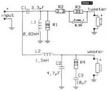
Audio crossovers are a class of electronic filter used in audio applications. The circuit above is a schematic of 2-way Cross-over to your sound system, the crossover is a device used to filter and divide the audio frequency between the bass, midrange and treble. It helps in sound quality, eliminating the distortion that occurs when there is a passage of undue frequencies for a particular speaker. Filters 2-way Cross-over to your sound system Circuit Diagram  

How to Installation A Car Stereo

Image
Car Stereo Installation Guide - Want to save some money? Ever wonder if you could do a car stereo installation yourself? Yes, you can do it yourself! Go ahead, spend that money on your hardware! Don’t spend it on labor. Besides, doing a car stereo installation yourself can be a very rewarding experience, not to mention you can learn a lot from it too. Nothing beats the feeling of seeing your “creation” in action, running smoothly and perfectly. But be very careful, you really won’t want to damage your expensive hardware. Well, most car audio hardware are no-brainers to install, you’d find that most of the time the parts have specially shaped sockets and slots etc. and would only fit where it’s supposed to be installed. Still, it’s best to proceed methodically. In a car stereo installation, you have to determine what kind of rig you’re going to put into your vehicle. If you’re a beginner, it’s best you do a car stereo installation if it’s just a simple system. You may want to leave ...

Sawtooth to Triangle Converter for Oscillator Circuit

Image
This wave shaper needs an input saw that goes from Vss to (ideally) Vdd. It works well with the 4069 VCO designed by René Schmitz. Any saw will work as long as the wave is centered halfway between the rails. It works as follows: The upper set of 2 linear mode gates provide an inverted and noninverted copy of the saw. The 3 logic gates at the bottom provide a sort of comparator that switches at halfway between the rails.   Sawtooth to Triangle Converter for Oscillator Circuit Diagram The 4007 provides 2 P-MOSFETs that alternately select the inverted or noninverted saw signal depending on where the saw is in it's cycle. This causes the ramp to reverse directions every half cycle. Any imperfection in the saw will show up in the resulting output. The linear mode gate furthest to the right provides soft clipping that turns the triangle wave into something like a sine wave. It sounds like it has fewer harmonics than the triangle. To use with FatMan sawtooth output: Power all IC...

Variable 5 to 20V DC Supply Circuit Diagram

Image
If you are looking for a low drop voltage regulator that can provide a power supply of 1A with an output voltage of between 5V and 20V DC, National Semiconductor LM2941 Low Dropout Adjustable Regulator is that you can pick to make use of. It's a typical dropout voltage of 0.5V which means that the input supply need only must be 0.5V DC over the desired output voltage. Its other features include internal short circuit current limit and reverse battery protection. As shown in the schematic below, the regulator has five pins which consists of the ON/OFF control, Input Voltage, Output Voltage, Ground & Adjustable pins. ON/OFF is used for the purpose of switching on & off of the regulator. The capacitors C1 & E1 are to be placed as close as feasible to the regulator. The output of the circuit can be varied by varying the worth of potentiometer VR1 from 5V DC to 20V DC. The input voltage is limited from five.5V DC to 30V DC. Resistor R1 must be greater than 1K. The worth of t...

How to Make a Dual Tone Siren Circuit

Image
This electronic siren gives out a continuously varying high amplitude sound. Since the supply voltage is not critical, it can be used in cars, motor cycles or at home. It can replace the ordinary call bell. - . The circuit consists of two separate free running multivibrator and an oscillator. More innovative circuits HERE. A free running or astable multivibrator is one which has two quasi-stable states and the output of one stag is connected to the input of the other through a coupling capacitor.Since both the states are quasi-stable, the output attained is continuously varying in nature i.e. high, low high low-.  The output is in the form low pulses, the frequency of which depends on the base biasing resistor and the coupling capacitor, When these resistances and condensers for both the stages are of different values, the output ` wave form is rectangular; this is because the time constant of the two quasi-stable states becomes different. If this time constant of the two, states i...

500W Cheap 12V to 220V inverter Circuit Diagram

Image
Build a simple 500W Cheap 12V to 220V inverter Circuit Diagram.  In this circuit 4047 is use to generate the square wave of 50hz and amplify the current and then amplify the voltage by using the step transformer. 500W Cheap 12V to 220V inverter Circuit Diagram How to calculate transformer rating The basic formula is P=VI and between input output of the transformer we have Power input = Power output For example if we want a 220W output at 220V then we need 1A at the output. Then at the input we must have at least 18.3V at 12V because: 12V*18.3 = 220v*1 So you have to wind the step up transformer 12v to 220v but input winding must be capable to bear 20A.   Source: www.circuitsproject.com

How to make 5 1 channel amplifier and speaker setup

Image
5.1 channel amplifier consists of 6 amplifiers 1 channel mono, which has certain specifications on each canals. Has 6 channel surround sound amplifier that consists of Front Left ,Center,Front Right ,Rear Left (Left Surround),Rear Right (Right Surround) , and LFE ( Subwoofer ).For clarity I give a simple illustration of the layout and the circuit for these speakers . 5.1 Speaker Setup Accoustic Field Generator Acoustic Field Generator is generating acoustic sound with surround effects are adjustable with a standard Dolby Surround, able to produce surround sound is good enough but not too much need of funds. Technological developments as if not only focused on one area alone but on all fronts. The development of technologies that exist today one of them is in the field of audio. With more advanced audio technology today not only as mere entertainment but has become a hobby, hobby is not cheap of course. Many audio enthusiasts trying to make music sound that sounded to be ...

10Mhz to 1 MHz Frequency Converter

Image
10Mhz to 1 MHz Frequency Converter Circuit Part ListIC1 7404 = 1 IC2 7490A = 1 R 1 K = 2 R 3.3 K = 1 C Trim Polymer 39 pF = 1 C Electrophoresis 4.7 uF 16V = 1 C Milar 47 nF 16 V = 1 C Milar 10 nF 16 V = 1 C Ceramic 68 pF 50 V = 1 

The 555 DC to AC Inverter Schematic

Image
This DC-to-AC inverter schematic produces an AC output at line frequency and voltage. The 555 is configured as a low-frequency oscillator, tunable over the frequency range of 50 to 60 Hz by Frequency potentiometer R4.  The 555 DC-to-AC Inverter Schematic The 555 feeds its output (amplified by Q1 and Q2) to the input of transformer T1, a reverse-connected filament transformer with the necessary step-up turns ratio. Capacitor C4 and coil L1 filter the input to T1, assuring that it is effectively a sine wave. Adjust the value of T1 to your voltage. Error fix: Pin 7 and 2 were reversed. Original pinout was correct. Parts List: R1 = 10K R2 = 100K R3 = 100 ohm R4 = 50K potmeter, Linear C1,C2 = 0.1uF  C3 = 0.01uF C4 = 2700uF Q1 = TIP41A, NPN, or equivalent transistor Q2 = TIP42A, PNP, or equivalent transistor  L1 = 1uH T1 = Filament transformer, your choice The output (in watts) is up to you by selecting different components. Input voltage is anywhere from +5V to +15Volt DC, ad...

Simple 12 to 120 Volt Inverter Circuit Diagram

Image
      This is the Simple 12 to 120 Volt Inverter Circuit Diagram. Ever needed a low power 120volt AC power source for your car, van or truck? Well this circuit should do the trick for you. It will supply 15 watts of AC power to a device. It should power lamps, shavers, small stereos and small appliances. If you draw to much power the circuit will shut down all by itself. The output of this circuit is a square wave so there may be some noticeable hum on audio units plugged into it. To reduce some of the hum increase the value of the output capacitor which is at .47uf now. That transistor in the circuit are high power PNP transistors. Radio Shack part number 276-2025 are good ones to use or TIP32. The transformer is a 24 volt 2 amp center tapped secondary Radio Shack part number 273-1512 or equivalent.   Simple 12 to 120 Volt Inverter Circuit Diagram