Posts

Showing posts with the label amplifier

60 watt power amplifier circuit with TDA1512

Image
This  is low noise power amplifier , high output power amplifier for full range speakers, but you can use the woofer speakers to this circuit .  Maximum output power 60 Watt with impedance 4 Ohms see circuit below :   Description for circuit above : Minimum Supply Voltage   : 12-Volt DC Maximum Supply Voltage  : 25-Volt DC Maximum Power Output : 60 Watts Impedance Speaker : 4 Ohm Current Voltage : 3A

120W amplifier with LM12

Image
This is power amplifier with basic amplifiy on IC LM12.

6 W hi fi audio power amplifier TDA2614

Image
FEATURES • Requires very few external components • No switch-on/switch-off clicks • Input mute during switch-on and switch-off • Low offset voltage between output and ground • Hi-fi in accordance with IEC 268 and DIN 45500 • Short-circuit proof and thermal protected • Mute possibility. GENERAL DESCRIPTION The TDA2614 is a power amplifier in a 9-lead single-in-line (SIL9) plastic medium power package. It has been especially designed for mains fed applications, such as TV and radio. Circuit diagram: 6 W hi-fi audio power amplifier TDA2614 Datasheet for TDA2614: Download

1200W power amplifier with sanken

Image
This 1200W power amplifier with sanken using a booster 8 sets sanken , the buffer using transistor D400 and B560 as much 2 sets , and to use part of the driver transistor B546/A940 and D401/C2168 . 1200W power amplifier with sanken have least 20 volts and the voltage to 70 volts maximum with three voltage is +,-,ground. 1200W power amplifier with sanken Power Output 2 X 600 Watt with 8 Ohm Impedance. Circuit audio amplifier 600 Watt Circuit of PCB so from 2  X 600 watts (looked down) Circuit of PCB (looked upon) The above is a circuit of ready to operate , just stay put booster. See also high power amplifier : 2800W High Power Amplifier

600W subwoofer audio amplifier with 20 channel mixer and parametric

Image
This picture below is about my setup subwoofer amplifier with 20 CH mixer and parametric . This amplifier use transformer 10 ampere to supply the power and 3 ampere transformer use to supply mixer and parametric.Elco capacitor that i use for the transformer 10 A, only 10000uF numbered 2. The circuit of amplifiers that i use which is 600 watt mono subwoofer amplifier . And booster amplifier only use 2 Sanken transistors. See picture subwoofer amplifier assemblies below : Looked over the side Front view Back top

150 watts power amplifier circuit

Image
Amplifier circuit is 150 watts power amplifier circuit is quite simple. This circuit requires only 5 pieces of transistors as the main component of reinforcement. There is no equalizer option on this amplifier circuit because it can be said of this series is very simple, so do not you compare it with that sold in the market which are usually equipped with various sound system and equalizer settings.  But to add to your collection circuit, this circuit is fairly easy and inexpensive to make and maybe one day you may need as a weak signal booster from your electronic circuit. Or you can also make this amplifier as an amplifier of high frequency signal from the output circuit animal repellent and I guarantee the results are very satisfactory. Power supply required is two-polarity power supply is + - 45 volts. Maximum power that can be obtained by this amplifier circuit is around 150 watts. As the volume control you can add potensio or variable resistor 10 Kohm in series at the input. ...

RF Fm 88 108 MHz 20W amplifier Circuit Diagram

Image
This Fm rf power amplifier has 2 transistors from Philips : BLV 10 and BLW 87. The 2 rf transistors work in class C and this fm amplifier has a total gain of 21dB ( 100 X ) and efficiency 55 – 65%. One low pass filter with 9 components ensures 60dB rejection on the second harmonic. There is no need for tune-up to cover the whole 88 – 108 MHz FM frequencies.  RF Fm 88 108 MHz 20W amplifier Circuit Diagram

50W Class B power amplifier circuit

Image
Power amplifier Class-B is the most popular operating modes, and possibly more than 99% of the current series of power amplifier designed and manufactered are of this class. Defining the Class-B is the amount of bias voltage that causes conduction of both output devices to overlap with the current and thus produce the minimum amount possible crossover distrosi. This Class-B power amplifier performance : Power Output________________________50W RL Impedance_______________________8R Distortion__________________________Below 0.0006% at 1 kHz and 50W/8R Slew rate___________________________Approximately 35V/us Noise______________________________-91dBu at the output EIN_______________________________-117dBu (referred to input) Frequency response__________________+0, -0.5dB over 20Hz-20kHz Part List : Resistor R1,R8____________________________10K R2,R3,R13________________________100R R4_______________________________150R R5,R10___________________________1K R6,R7____________________________68R ...

Stereo 175 watt amplifier or 350 watt mono amplifier STA517B

Image
350 watt mono amplifier Stereo circuit in datasheet here

Mini and simple power amplifier circuits

Image
What is the meaning of the picture above? The above picture is a miniature audio amplifier and very simple. Here I will give an audio amplifier schematic is very simple which only requires a few components only, can be seen under this scheme. See from above scheme may occur to you, certainly cheap enough to make this amplifier and quite easy to make. The above simple audio amplifier circuit using an IC as the main amplifier and accompanied by other components. IC used is S1513, which requires a supply voltage ranging from 1.5 volts to 6 volts. And only 0.1 W output power with 4 ohm impedance. For a list components can be seen below. Part list C1 = 100nF C2 = 100uF C3 = 3n3F C4 = 1uF C5 = 1uF U1 = S1513

4 x 35 Watt car audio amplifier

Image
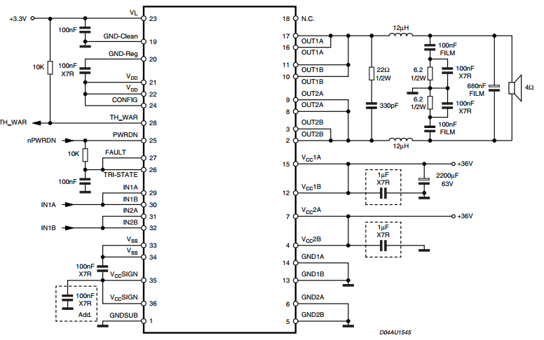
General Description: The AN7560Z is an audio power IC developed as the sound output of car audio (35 W by 4-ch.). A capacitor and resisitor to stop oscillation are built in between the output pin and GND so that a space saving of set is possible. Also, it incorporates a perfect muting circuit with out shock noise so that a shock noise design under the set transient condition can be made easily when used together with its standby function. In addition, it incorporates various protection circuits to protect the IC from destruction by GND-open-shortcircuit to ground and power supply surge which are the important subject of power IC protection. This IC will largely contribute to a high reliability design of the equipment. Circuit Diagram: 4 x 35 Watt car audio amplifier Datasheet for AN7560:  Download

Car amplifier circuit with IC BA532

Image
Minimum Voltage required for this circuit  6 volt and maximum voltage 18 volt . Its can use to amplifier on the electronic devices such us Radio , DVD , MP4 , MP5 , and etc. To amplify the signal sound to audio sound , If  you want to bring amplfier you can use the 6V  rechargeable battery is able to turn it. What use the rechargeable battery ? because with rechargeable battery when battery runs out , you can charge back. See Amplifier schematic with IC BA511 below : Click to view large Maximum output power 10 Watt with impedance 4 ohm. The circuit is mono amplifier. You can use the circuit to car amplifier because support to low power subwoofer speaker

Class A amplifier Circuit Diagram

Image
This is the simple Class-A amplifier Circuit Diagram. This circuit allows a class-A amplifier to drive a low impedance speaker and has a low quiescent current. The 220R in series with the speaker limits the "wasted" current to about 20mA max as the transistor is generally biased at mid-voltage. Class-A amplifier Circuit Diagram However the transistor will be almost directly driving the speaker when a signal is being processed and the only limitation is the ability of the 220R to discharge the 100u during each cycle.The circuit is called a signal by-pass as the signal by-passes the 220R and drives the speaker directly (via the 100u).

3 Watt power amplifier schematic

Image
This time I will share a circuit of schematis power amplifier with LM380 IC that has similarities with LM384. Enough with just a few components you have to make this power amplifier circuit . All components with relatively low prices and making a fairly easy. For this amplifier output power has 3W with 4 ohm impedance. Indeed , this amplifier has the output is quite low and certainly will not be maximal if it works on the speakers with high power. Component List : Resistor R1______________47K R2______________2.7R 2W Capacitor C1______________10uF C2______________470uF C3______________100n C4______________100n IC IC1_____________LM380 , LM384

Subwoofer amplifier with 30W output power

Image
Amplifier circuit is very suitable for use in subwoofer amplifier system based on IC SI1030G. Amplfier has 30W output with 8 ohm impedance. Supply voltage required minimum of 12 volts and a maximum of up to 22 volts DC. Component List : R1 = 100K R2 = 1R C1 = 2.2uF C2 = 100uF C3 = 47uF C4 = 100nF C5 = 10uF C6 = 47uF C7 = 100uF IC = SI1020GL , SI1030G