Posts

Showing posts with the label current

High current output switching power supply

Image
This is low voltage high-current ouput , switching dc power supplly wiht input 220 Volts AC , In this circuit , an St2 diac relaxation oscilator, Q3 , C1 , and the diac , initiates conduction of the output switching transistor Q1, the on time of which is maintained constant by a separate timing / commutation network consisting of Q2 , C2 ,SUS , and SCR 1. See schmeatic diagram below : The output voltage , consequently , is independent on the duty cycle . To compensate for unwanted variations of output voltage because of input voltage or load resistance fluctuations , an H11C wired as a liniear - model unilateral pnp transistor in a stable different amplifier configuration is connected into the galvanically isolated negative- feedback loop.

current transformer

Image

30 VDC Stabilized power supply with current control 0 002 3 A

Image
  General Description This is a high quality power supply with a continuously variable stabilised output adjustable at any value between 0 and 30VDC. The circuit also incorporates an electronic output current limiter that effectively controls the output current from a few milliamperes (2 mA) to the maximum output of three amperes that the circuit can deliver. This feature makes this power supply indispensable in the experimenters laboratory as it is possible to limit the current to the typical maximum that a circuit under test may require, and power it up then, without any fear that it may be damaged if something goes wrong. There is also a visual indication that the current limiter is in operation so that you can see at a glance that your circuit is exceeding or not its preset limits.     Technical Specifications - Characteristics Input Voltage: ................ 24 VAC Input Current: ................ 3 A (max) Output Voltage: ............. 0-30 V adjustable Outp...

AC Line Current Detector Circuit Diagram

Image
This circuit diagram will detect AC line currents of about 250 mA or more without making any electrical connections to the line. Current is detected by passing one of the AC lines through an inductive pickup (L1) made with a 1 inch diameter U-bolt wound with 800 turns of #30 - #35 magnet wire. The pickup could be made from other iron type rings or transformer cores that allows enough space to pass one of the AC lines through the center. Only one of the current carrying lines, either the line or the neutral should be put through the center of the pickup to avoid the fields cancelling. I tested the circuit using a 2 wire extension cord which I had separated the twin wires a small distance with an exacto knife to allow the U-bolt to encircle only one wire. AC Line Current Detector Circuit Diagram The magnetic pickup (U-bolt) produces about 4 millivolts peak for a AC line current of 250 mA, or AC load of around 30 watts. The signal from the pickup is raised about 200 times at the outpu...

Constant Current Dummy Load

Image
The purpose of the device is for when you need a constant load to test things like power supplies, or batteries. No matter what the voltage coming out of the power supply, the constant current dummy load will adjust automatically to provide the same amount of current. [ ]

Current transformer functionality picture

Image

4 20 mA current signal in Instrumentation

Image
The 4 - 20 mA signal is an extremely popular signal specification in instruments. The 4 to 20 mA signal provides "live zero" function. i.e. in the event of a wire break, the signal drops to zero mA. This can be used to detect wire break or sensor failure. This is a crucial advantage of the 4 to 20 mA format. Being a Current signal, it is also less susceptible to external interference. The 4 to 20 mA format works by varying the resistance to a constant source voltage. The sensor consists of a transistor which regulates the current passing through it in accordance with the measured value. Sensors which use this format can be categorized into active and passive transducers. Active transducers are devices which can provide the system voltage as well as regulate the current. Passive devices require an external voltage and only regulate the current. Another advantage of this 4 to 20 mA format is that it can be easily converted into a voltage signal by means of a res...

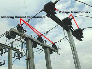
metering current transformer

Image