Posts

Showing posts with the label Build

How to Build Unregulated Linear Power Supply
Image
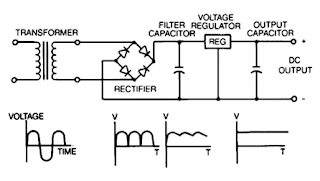
Unregulated power supplies contain four basic components: transformer, rectifier, filter capacitor, and a bleeder resistor. This type of power supply, because of Us simpticity, is the least costly and most reliable for low power requirements. The disadvantage is that the output voltage is not constant It will vary with the input voltage and the load current, and the ripple is not suitable for electronic applications. The ripple can be reduced by changing the filter capacitor to an LC (inductor-capacitor) filter but the cost to make this change would make use of the regulated linear power supply a more economical choice.

Build a Simple Audio Amplifier 2800W Circuit Diagram

Image
How to Build a Simple Audio Amplifier 2800W Circuit Diagram . This is a Mono high power amplifier is actually a powerful 1400 W, but if this high power amplifier circuit is doubled and you want to create stereo, high power amplifier the necessary components and pcb requires two-fold. So if the stereo high power amplifier 2 X 1400W. Schematic Circuit diagram is still less by looking at the circuit that was so below, the finished circuit has been added with a gains using JRC4558 IC by the two and the picture ic where it can be seen below.  For circuit buffers, drivers, and booster use multiple transistors and other components (can be seen listed component). And high power amplifier project that is so below is just part of the buffer and driver while the booster has not been made​​. For additional transistors in the booster or high power amplifier end scheme can be found Booster output power amplifier.  Audio Amplifier 2800W Circuit Diagram Part List : Resistor R1_____560Ω R2___...

Build a Varying Brightness AC Lamp Circuit

Image
Varying Brightness AC Lamp Circuit , an SCR is used to slowly vary the intensity of a 120 volt light bulb by controlling the time that the AC line voltage is applied to the lamp during each half cycle. Varying Brightness AC Lamp Circuit Diagram Caution: The circuit is directly connected to the AC power line and should be placed inside an enclosure that will prevent direct contact with any of the components. To avoid electrical shock, do not touch any part of the circuit while it is connected to the AC power line. A 2K, 10 watt power resistor is used to drop the line voltage down to 9 volts DC. This resistor will dissipate about 7 watts and needs some ventilation. Operation: A couple NPN transistors are used to detect the beginning of each half cycle and trigger a delay timer which in turn triggers the SCR at the end of the delay time. The delay time is established by a current source which is controlled by a 4017 decade counter. The first count (pin 3) sets the current to a minimum whi...

Build a 9V Wireless Microphone FM Transmitter

Image
This FM transmitter circuit can be used as a wireless microphone,  can be received by an ordinary 88- to 108-MHz FM broadcast receiver. For the power supply, this transmitter circuit is powered by a 9 V battery. To comply with the radiation limit of FCC rules, keep the antenna length under 12 inches. L1 is 6 turns of #24 wire wound around a pencil or a 1/4″ form, with turns spacing of 1 wire diameter. C6 is a gimmick capacitor which has value about 1 pF.  9V Wireless Microphone FM Transmitter Circuit Diagram

Build a 10 LED Bar Dot VU Meter Circuit based LM3915

Image
Build a 10 LED Bar Dot VU meter circuit based LM3915 . It differs in many respects from other applications on the same chip. The circuit is intended for those who want a VU meter that is connected directly to the output of an power amplifier.  10 LED Bar Dot VU Meter Circuit based LM3915 Circuit Diagram It’s possible to adjust the sensitivity to work with amplifiers that have different output power, you just need to change the value of R1 according to Table 1. In case you did’n find the exact resistor value, then choose the next standard value (for example if you cannot find 33K ohm, then find the 36K ohm), or if you want maximum accuracy you need to put resistors in series or in parallel to achieve the correct value.   You can use various types of LEDs (round or square) to get the visual and aesthetic result you want. The switch S1 will allow you to choose whether VU meter will work as a bar or one by one (dot). In position ON [closed switch], the LED operation is Bar, while ...

Build a Fast Breaker Circuit Diagram

Image
This is the simple and Fast Breaker Circuit Diagram . This 115 Vac, electronic circuit breaker uses the low drive power, low on resistance and fast turn off of the TMOS MTM15N50. The trip point is adjustable, LED fault indication is provided and battery power provides complete circuit isolation. The two `circuit breaker` terminals are across one leg of a full wave diode bridge consisting of D1-D4. Normally, Q1 is turned ON so that the circuit breaker looks like a very low resistance.   Fast Electronic Breaker Circuit Diagram One input to comparator Ul is a fraction of the internal battery voltage and the other input is the drop across zeners D6 and D7 and the voltage drop across R1. If excessive current is drawn, the voltage drop across Rl increases beyond the comparator threshold (determined by the setting of R6), U1 output goes low, Q1 turns OFF, and the circuit breaker `opens.` When this occurs, the LED fault indicator is illuminated.

Build a Fog Lamp Switch Circuit Diagram

Image
This is a simple Fog Lamp Switch Circuit Diagram. This circuit recommended to have a rear fog light on a trailer with the additional requirement that, when the trailer is coupled to the car, the rear fog light of the towing car has to be off. The circuit shown here is eminently suitable for this application. The circuit is placed near the rear fog light of the car. The 12-V connection to the lamp has to be interrupted and is instead connected to relay contacts 30 and 87A (K1, K3). When the rear fog light is turned on it will continue to operate normally.  Fog Lamp Switch Circuit Diagram If a trailer with fog light is now connected to the trailer connector (7- or 13-way, K2), a current will flow through L1. L1 is a coil with about 8 turns, wound around reed contact S1. S1 will close because of the current through L1, which in turn energizes relay Re1 and the rear fog light of the car is switched off. The fog light of the trailer is on, obviously. The size of L1 depends on reed conta...

Build Improvised Fan Grills

Image
Making your own grill for your fans would be a lot easier and cheaper. You could use all materials that can be found in your home. Your main component would be your old fan, removed its metal ring and you can now measure the desired length or size of grid that you will be needed. Cut the grid across so it will be easier to cut, then place it in the tower and use the same screw you removed in the fan. Now you can put the grid holding fan back in its place. Clean up and you can now use your very own fan grills that cost almost nothing but your patience.

Build a Curve Tracer Circuit Diagram

Image
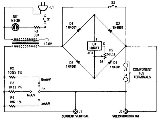
How to Build a Curve Tracer Circuit Diagram ? This is the simple Curve Tracer Circuit Diagram. This circuit Useful for checking diodes, transistors, triacs, SCRs, resistors, and LEDs, this curve tracer should prove useful in the experimenter`s lab.   Curve Tracer Circuit Diagram It displays the volt-ampere characteristic of a two-ter-minal device on an oscilloscope. This is a simple block diagram of the EZ-Curve. Current-limited AC signals are passed through both the device under test and a precision resistor to yield current and voltage readings.

Build 12V to 9V DC Converter

Image
To get a more precise output voltage, replace zener diode Z1 with 10V and R1 with a 1Kilo ohm potentiometer. A Coolrib for Q1 is optional but highly recommended. You can replace Q1 for a more robust type to get more output amps depending on your requirements. Simple circuit to power your 9 volt cassette recorder and other stuff. Parts List: R1 = 560 ohm C1 = 1000uF/40V, Electrolytic C2 = 10uF/25V, Electrolytic C3 = 330nF, Ceramic Z1 = 9.1V, 1watt zener Q1 = ECG184, NTE184 

Build a Radio Wave Alarm

Image
This simple circuit is sure to have the police beating a path to your door- however, it has the added advantage of alerting you to their presence even before their footsteps fall on the doormat. Simple Radio Wave Alarm Circuit Diagram : Notes : The circuit transmits on Medium Wave (this is the small problem with the police). IC1a, together with a sensor (try a 20cm x 20cm sheet of tin foil) oscillates at just over 1MHz. This is modulated by an audio frequency (a continuous beep) produced by IC1b. When a hand or a foot approaches the sensor, the frequency of the transmitter (IC1a) drops appreciably. Suppose now that the circuit transmits at 1MHz. Suppose also that your radio is tuned to a frequency just below this. The 1MHz transmission will therefore not be heard by the radio. But bring a hand or a foot near to the sensor, and the transmitter's frequency will drop, and a beep will be heard from the radio. Attach the antenna to a multiplug adapter that is plugged into the mains, a...

Build a PC Based Timer Circuit Diagram

Image
Timers are very useful both for industrial applications and household appliances. Here is a PC-based timer that can be used for controlling the appliances for up to 18 hours. For control, the timer uses a simple program and interface circuit. It is very cost-effective and efficient for those who have a PC at workplace or home. The tolerance is ±1 second. The circuit for interfacing the PC’s parallel port with the load is very simple. It uses only one IC MCT2E, which isolates the PC and the relay driver circuits. The IC prevents the PC from any short circuit that may occur in the relay driver circuit or appliance. The glowing of LED1 indicates that the appliance is turned on. Transistor BC548 is used as the relay driver. The program code is written in ‘C’ language and compiled using ‘Turbo C’ compiler. When the program is run, it prompts the user to input the time duration in seconds or minutes to control the appliance. After entering the required timing, press any key from the keyboard...

Build a Voltage to Frequency Converter Circuit Diagram 3

Image
Build a Voltage to Frequency Converter Circuit Diagram 3 . The input voltage, V1, causes C1 to charge and produce a ramp voltage at the output of the 741 op amp. Diodes D1 and D2 are four-layer devices. When the voltage across C1 reaches the breakover voltage of either diode, the diode conducts to discharge C1 rapidly and the op amp output goes abruptly to zero. This rapid discharge action applies a narrow pulse to G1 and G2. Positive discharge pulses produced by a positive V1 are coupled to the output only through G1, while negative pulses are coupled only through G2.  Because of the forward break-over current of diodes D1 and D2, the circuit won`t operate below a minimum input voltage. An increase of R1 increases this minimum voltage and reduces the circuit`s dynamic range. The minimum input voltage with R1 at 1 Kn is in the range of 10 to 50 m V. This input dead zone, when input signal V1 is near zero is desirable in applications that require a signal to exceed a certain level b...

Build 20W MOSFET Power Amplifier Circuit with IFR9520 IFR520

Image
As we are like to show you about audio and sound circuit ,I found the circuit which is good one for power amplifier with one MOSFET. The output power of an operational amplifier is often increased by a complementary emiter follower. It can also be done with a MOSFET,but it is not a good idea to connect such a device as a complementary souce follower because the maximum output voltage of the opamp is then reduced appreciably by the gate-source control voltage of the MOSFET ,which can be a couple of volts. 20W MOSFET Power Amplifier Circuit with IFR9520,IFR520 20W power amp MOSFET Another approach is to connect two MOSFETs as a complementary drain follower.The (alternating) output current provided by the MOSFETs is limited by the level of the supply voltages and the saturateion voltages of T3 and T4 Resistor R8,together with R9,provides feedback for both the opamp and MOSFETs . The open-loop amplification of the opampis,therefore,increased by (1+R8/R9).the closed-loop amplification of th...

How to Build a Shake Tic Tac LED Torch

Image
In the diagram, it looks like the coils sit on the “table” while the magnet has its edge on the table. This is just a diagram to show how the parts are connected. The coils actually sit flat against the slide (against the side of the magnet) as shown in the diagram: Shake Tic Tac LED Torch Circuit Diagram The output voltage depends on how quickly the magnet passes from one end of the slide to the other. That's why a rapid shaking produces a higher voltage. You must get the end of the magnet to fully pass though the coil so the voltage will be a maximum. That’s why the slide extends past the coils at the top and bottom of the diagram. The circuit consists of two 600-turn coils in series, driving a voltage doubler. Each coil produces a positive and negative pulse, each time the magnet passes from one end of the slide to the other. The positive pulse charges the top electrolytic via the top diode and the negative pulse charges the lower electrolytic, via the lower diode. The voltage a...

Build a Digital Electronic Lock Circuit Diagram

Image
This Digital Electronic Lock Circuit Diagram shown below uses 4 common logic ICs to allow controlling a relay by entering a 4 digit number on a keypad. The first 4 outputs from the CD4017 decade counter (pins 3,2,4,7) are gated together with 4 digits from a keypad so that as the keys are depressed in the correct order, the counter will advance. As each correct key is pressed, a low level appears at the output of the dual NAND gate producing a high level at the output of the 8 input NAND at pin 13. Digital Electronic Lock Circuit Diagram The momentary high level from pin 13 activates a one shot circuit which applies an approximate 80 millisecond positive going pulse to the clock line (pin 14) of the decade counter which advances it one count on the rising edge. A second monostable, one shot circuit is used to generate an approximate 40 millisecond positive going pulse which is applied to the common point of the keypad so that the appropriate NAND gate will see two logic high levels whe...

How to Build AC Line Current Detector

Image
This circuit will detect AC line currents of about 250 mA or more without making any electrical connections to the line. Current is detected by passing one of the AC lines through an inductive pickup (L1) made with a 1 inch diameter U-bolt wound with 800 turns of #30 - #35 magnet wire. The pickup could be made from other iron type rings or transformer cores that allows enough space to pass one of the AC lines through the center.  Only one of the current carrying lines, either the line or the neutral should be put through the center of the pickup to avoid the fields cancelling. I tested the circuit using a 2 wire extension cord which I had separated the twin wires a small distance with an exacto knife to allow the U-bolt to encircle only one wire. AC Line Current Detector Circuit Diagram The magnetic pickup (U-bolt) produces about 4 millivolts peak for a AC line current of 250 mA, or AC load of around 30 watts. The signal from the pickup is raised about 200 times at the output of th...

Build a Fast Breaker Circuit Diagram

Image
This is the simple and Fast Breaker Circuit Diagram . This 115 Vac, electronic circuit breaker uses the low drive power, low on resistance and fast turn off of the TMOS MTM15N50. The trip point is adjustable, LED fault indication is provided and battery power provides complete circuit isolation. The two `circuit breaker` terminals are across one leg of a full wave diode bridge consisting of D1-D4. Normally, Q1 is turned ON so that the circuit breaker looks like a very low resistance.   Fast Electronic Breaker Circuit Diagram One input to comparator Ul is a fraction of the internal battery voltage and the other input is the drop across zeners D6 and D7 and the voltage drop across R1. If excessive current is drawn, the voltage drop across Rl increases beyond the comparator threshold (determined by the setting of R6), U1 output goes low, Q1 turns OFF, and the circuit breaker `opens.` When this occurs, the LED fault indicator is illuminated.

Build a 3 Channels Audio Splitter Amplifier Circuit Diagram using TL084

Image
This is the schematic diagram of 3 channels audio splitter amplifier circuit which built using op-amp IC TL084. The 3 channels amplifier output distribution applies a single TL084.   3 Channels Audio Splitter Amplifier Circuit Diagram The very first step is to capacitive coupling having a p. 1.0 ~ electrolytic capacitor. The entries are railways Vee Y2 or 4.5 V. This enables working with an individual 9V power source. A voltage gain of 10 (1 M?/100 Kohm) is obtained in the first stage, as well as the other three floors are connected as a unity gain voltage followers. Every single output stage drives independently through an amplifier output 50 pF capacitor towards the resistance of 5.1 k ohm load. The response range is flat from 10 Hz to 30 kHz.

How to Build 1 2 30V 1 5A Variable Regulated Power supply Circuit

Image
How to Build 1.2-30V/1.5A Variable Regulated Power supply, This is simple 1.2-30V/1.5A variable regulated power supply circuit diagram The 110V-AC coming from the powercord is fed to the transformer TR1 via the on-off switch and the 500mA fuse. The 30vac output (approximately) from the transformer is presented to the BR1, the bridge-rectifier, and here rectified from AC (Alternating Current) to DC (Direct Current). If you don't want to spend the money for a Bridge Rectifier, you can easily use four general purpose 1N4004 diodes. The pulsating DC output is filtered via the 2200µF capacitor (to make it more manageable for the regulator) and fed to 'IN'-put of the adjustable LM317 regulator (IC1). The output of this regulator is your adjustable voltage of 1.2 to 30volts varied via the 'Adj' pin and the 5K potmeter P1. The large value of C1 makes for a good, low ripple output voltage.  1.2-30V/1.5A Variable Regulated Power supply Circuit Diagram Why exactly 1.2V and not...