Posts

Showing posts with the label Booster

Hydrophone Booster Amplifier HA2 Circuit Diagram

Image
The HP series Hydrophone Booster Amplifier (HA2) amplifies low-level hydrophone signals over a wide range of frequencies. It has a minimum gain of 25dB and an input and output impedance of 50Ω. The HA2 is designed for use with either Precision Acoustics membrane hydrophone or Precision Acoustics HP Series Hydrophone Measurement System, which is shown in Fig 1. Hydrophone Booster Amplifier (HA2) Circuit Diagram Alternatively, the HA2 may be used when the acoustic signal is provided by a high output impedance hydrophone, such as a GEC-Marconi membrane device, or a conventional hydrophone. In this instance a BNC/MCX adaptor is used which connects directly to the HP Series Submersible Preamplifier, using it as a buffer amplifier, (i.e. the standard Precision Acoustic HP Series configuration shown in Fig 1 is used, but without the interchangeable probe). The HA2 amplifier is straightforward to use but the following points should be noted: The output of the amplifier should be correctly te...

Hydrophone Booster Amplifier HA2

Image
The HP series Hydrophone Booster Amplifier (HA2) amplifies low-level hydrophone signals over a wide range of frequencies. It has a minimum gain of 25dB and an input and output impedance of 50Ω. The HA2 is designed for use with either Precision Acoustics membrane hydrophone or Precision Acoustics HP Series Hydrophone Measurement System, which is shown in Fig 1. Alternatively, the HA2 may be used when the acoustic signal is provided by a high output impedance hydrophone, such as a GEC-Marconi membrane device, or a conventional hydrophone. In this instance a BNC/MCX adaptor is used which connects directly to the HP Series Submersible Preamplifier, using it as a buffer amplifier, (i.e. the standard Precision Acoustic HP Series configuration shown in Fig 1 is used, but without the interchangeable probe). . The HA2 amplifier is straightforward to use but the following points should be noted: The output of the amplifier should be correctly terminated in 50Ω before operation. The HA2 amplifi...

Bass Booster with TL072

Image
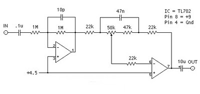
The following is megabass circuit schematic (rangkaian megabass) . The megabass circuit is a modified Baxandall tone control with no bass cut and no treble control. It boosts frequencies from about 30Hz to 160Hz can boost by 14dB. Bass Booster Schematics Note: The input capacitor can be replaced with a .01uf cap if you wish. The 10pf capacitor is optional and will start rolling off everything over 15kHz. 5pf will double this to 31kHz. The tone control requires a low impedence input. If you already have a low impedence input, the input buffer can be removed. However, the output is inverted. The opamp is not critical. A 4558 would be just fine. I do not show the parts for the +4.5 reference. Here is the +4.5 voltage divider I used. IC A4558 Pinning The A4558 is a monolithic Integrated Circuit designed for dual operational amplifier. Absolute maximum ratings of A4558 Ap-amp Supply voltage VCC 20 or ±10 V Differential input voltage VIND 20 V Input voltage VIN ±10 V Power Dissipation PD 300...

FM Booster Diagram Circuit

Image
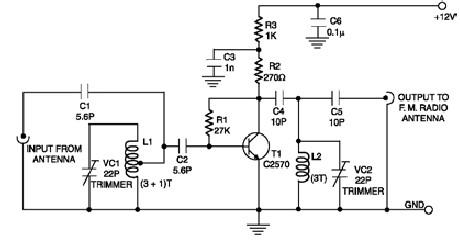
Description A low-cost circuit of an FM booster that can be used to listen programs from distant FM stations clearly. The circuit comprises a common-emitter tuned RF preamplifier wired around VHF/UHF transistor 2SC2570 ( C2570). This FM booster circuit is constructed using few common components ( not require some special components ) and provide a very good gain . To calibrate this circuit you need to adjust input/output trimmers (VC1/VC2) for maximum gain. Input coil L1 consists of four turns of 20SWG enamelled copper wire (slightly space wound) over 5mm diameter former. It is tapped at the first turn from ground lead side. Coil L2 is similar to L1, but has only three turns. Both of the trimmers are 22pF value .This FM radio signal booster needs to be powered by a 12 volts DC power supply . Circuit Diagram Source - http://www.electroniq.net/radio-frequency/fm-booster-schematic-circuit.html

USB Power Booster

Image
Power shortage problems arise when too many USB devices connected to PC are working simultaneously. All USB devices, such as scanners, modems, thermal printers, mice, USB hubs, external storage devices and other digital devices obtain their power from PC. Since a PC can only supply limited power to USB devices, external power may have to be added to keep all these power hungry devices happy. This circuit is designed to add more power to a USB cable line. A sealed 12V 750 mA unregulated wall cube is cheap and safe. To convert 12 V to 5 V, two types of regulators, switching and linear are available with their own advantages  and drawbacks. USB Power Booster Circuit Diagram The switching regulator is more suitable to this circuit because of high efficiency and compactness and now most digital circuits are immune to voltage ripple developed during switching. The simple switcher type LM2575-5 is chosen to provide a stable 5V output voltage. This switcher is so simple it just needs three...

Tube Town Banana Booster Layout

Image