Posts

Showing posts with the label Tracer

Build a Curve Tracer Circuit Diagram
Image
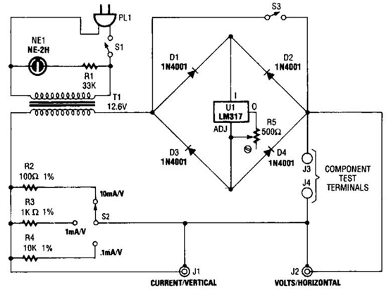
How to Build a Curve Tracer Circuit Diagram ? This is the simple Curve Tracer Circuit Diagram. This circuit Useful for checking diodes, transistors, triacs, SCRs, resistors, and LEDs, this curve tracer should prove useful in the experimenter`s lab.   Curve Tracer Circuit Diagram It displays the volt-ampere characteristic of a two-ter-minal device on an oscilloscope. This is a simple block diagram of the EZ-Curve. Current-limited AC signals are passed through both the device under test and a precision resistor to yield current and voltage readings.

Pulse Generator And Signal Tracer

Image
Dual-purpose test-instrument, Very simple circuitry, 1.5V Battery-operated This simple circuit generates narrow pulses at about 700-800Hz frequency. The pulses, containing harmonics up to the MHz region, can be injected into audio or radio-frequency stages of amplifiers, receivers and the like for testing purposes. A high-pitched tone can be heard from the speaker of the device under test when all is working properly. The clip must be connected to the ground of the device under test, touching with the probe the different stages of the circuit, starting from the last stage and going up towards the first. When the tone is no longer heard, the defective stage has been found. Connecting an earclip or headphone to J1, the circuit will automatically change into a two-stage amplifier and any audio signal coming from the device under test and picked-up by the probe will be heard through the headphones. The testing of a circuit should be made in the reverse manner, i.e. starting from the first ...