Posts

Showing posts with the label Stereo

Combine stereo input to one output

Image
Here , I will give a circuit of schemes that are used to combine 2 pieces input or stereo to 1 input mono. Why 2 inputs in to one because, if we need a stereo amplifier we want to become a stronger by combining the two input into one input, so that a higher power output. Actually without any circuit above we can combine stereo amplifier into mono, but the sound output less than the maximum , need for this additional combiner circuit. Part List = R1______150K R2______920R R3______150K R4______920R R5______920R U1______NE5532 For balance _: R1 / R2=R3 / R4 For balance _: R1 = R3 Gain ______: R5 / R1 = R5 / R3

Stereo Low power audio amplifier

Image
Audio amplifier circuit has a power output of 2 x 2.3 Watt, which uses IC KA2206, KA22061, LA4180, LA4182, LA4183, LA4550, LA4555, LA4558. The required voltage for at least 6 volts to 13 volts DC maximum. Component takes is a ic that I mentioned above one of them, and several capacitors elco. This Schematics low power amplifier Component Description C1 = 1uF C2 = 100uF C3 = 100uF C4 = 100uF C5 = 0.1uF C6 = 470uF C7 = 1uF C8 = 100uF C9 = 100uF C10 = 100uF C11 = 0.1uF C12 = 470uF ICs can use the ic which I mention above for each ic datasheet can be seen itself.

Project of Balanced Output Board For The Stereo DAC

Image
This add-on board is designed to provide a pair of balanced audio outputs for the High-Quality Stereo DAC (Digital to Analog Converter). Two 3-pin male XLR connectors are used for the new outputs and they can either replace or augment the existing unbalanced outputs without affecting their performance. Balanced audio is used in recording studios and on stage because of its improved noise immunity. Picture of the project:      This is due to the fact that the signal is sent differentially (ie, as two signals 180° out of phase) and then converted to a single-ended voltage signal at the far end. If any noise is picked up in the cable, it affects the two out-of-phase signals equally so that when the signals are subsequently subtracted, most of the noise is eliminated. Parts layout: In addition, the DAC’s performance at the balanced outputs generally exceeds that of the unbalanced outputs, although only by a small margin. The signal-to-noise ratio, frequency response and chann...

Stereo Power Amplifier Using IC 7905

Image
79xx is a widely known series of low-cost, fixed-negative-voltage regulators. These integrated circuits are available with output current of 100-150 mA (L series), 0.4-0.5A (M series), up to 1A (standard series), etc. They can be used in many applications other than regulators, audio power amplifier being one of them.  As shown in the circuit diagram, a simple stereo audio amplifier is built around two 7905 negative-voltage regulators (IC1 and IC2) and a few discrete components. The 7905 IC (a -5V regulator) used here is readily available. However, the circuit will also work with other 79XX regulators if appropriate power supply is used. Both channels shown in the diagram are identical. Hence the description below is only for the first channel. The quality of the output signal is within acceptable limits. Circuit diagram : Stereo Power Amplifier Circuit Diagram Regulator IC 7905 works as an amplifier for the voltages applied to common pin2 (Ground or GND). The minimal voltage dro...

A Pioneer In Their Own Right The Pioneer Car Stereo

Image
Look at any good car stereo system and you’ll probably see a Pioneer car stereo unit plugged into the console. Alongside with quality speakers and a strong lineup of accessories like LCD panels and navigational devices, Pioneer products/Pioneer car stereos have earned a huge following the world over.   The Pioneer Company is a Tokyo-based corporation, and is one of the world leaders in digital entertainment products. The Pioneer Company was first founded in 1938 in Tokyo as a small radio and speaker repair shop business but today, they are recognized as a leader in technology advancements in the consumer electronics industry. The company is truly deserving of their name. They are respected for many innovations such as interactive cable TV, the Laser Disc player, developing the first Compact Disc player for the car and the first detachable face car stereo, DVD and DVD recording, plasma display, and organic electroluminescent display. Their strength in optical disc and display techn...

Simple FM stereo decoder circuit using MC1310P IC

Image
Simple FM stereo decoder circuit using MC1310P IC via next.gr

Mobile Car Stereo Player

Image
Using a mobile phone while driving is dangerous. It is also against the law. However, you can use your mobile phone as a powerful music player with the help of a stereo power amplifier. This does away with the need of a sophisticated in-dash car music system. Most mobile phones have a music player that offers a number of features including preset/manual sound equalisers. They have standard 3.5mm stereo sockets that allow music to be played through standard stereo headphones/sound amplifiers. Nokia 2700 classic is an example. Circuit diagram : Mobile Car Stereo Player Circuit Diagram A car audio amplifier with 3.5mm socket can be designed and simply connected to the mobile phone output via a shielded cable with suitable connectors/jacks (readymade 3.5mm male-to-male connector cable is a good alternative). Fig. 1 shows the circuit of car stereo player. It is built around popular single-chip audio power amplifier TDA1554Q (IC1). The TDA1554Q is an integrated class-B power amplifier i...

1 W Home Stereo Amplifier Circuit Diagram

Image
This is a one watt home stereo amplifier module project using the KA2209 IC from Samsung, which is equivalent to the TDA2822. It operates from 3-12V DC & will work from a battery since the dormant current drain is low. It requires no heat sink for normal use. The input & output are both ground referenced. Maximum output will be obtained with a 12V power supply & 8 ohm speaker, however it is suitable for driving headphones from a supply as low as 3V. The Specifications of the home stereo amplifier : D.C. input : 3 – 12 V at 200 – 500 mA max Idle current : approx. 10 mA Power output : > 1 Watt max. 4-8 ohms, 12V DC Freq. Resp. : approx. 40 Hz to 200 kHz, 8 ohm, G=10 THD : < 1 % @ 750 mW, 4-8 ohm, 12V Gain : approx. x10 (20 dB) OR x100 (40dB) S/N ratio : > 80 dB, G = 20 dB Sensitivity : < 300 mV, G = 20 dB Input Impedance : approx. 10 k ohm Description   The gain is adjustable from ten to 100, i.e. twenty to 40 dB. Start with feedback resistors R1 and R3 of 1k...

32W Stereo Audio Amplifier

Image
32W Stereo Audio Amplifier

How to Installation A Car Stereo

Image
Car Stereo Installation Guide - Want to save some money? Ever wonder if you could do a car stereo installation yourself? Yes, you can do it yourself! Go ahead, spend that money on your hardware! Don’t spend it on labor. Besides, doing a car stereo installation yourself can be a very rewarding experience, not to mention you can learn a lot from it too. Nothing beats the feeling of seeing your “creation” in action, running smoothly and perfectly. But be very careful, you really won’t want to damage your expensive hardware. Well, most car audio hardware are no-brainers to install, you’d find that most of the time the parts have specially shaped sockets and slots etc. and would only fit where it’s supposed to be installed. Still, it’s best to proceed methodically. In a car stereo installation, you have to determine what kind of rig you’re going to put into your vehicle. If you’re a beginner, it’s best you do a car stereo installation if it’s just a simple system. You may want to leave ...

Low Cost Stereo Level Indicator Circuit Diagram

Image
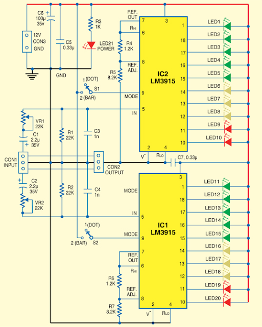
Usually, Low-Cost Stereo Level Indicator home stereo power amplifiers don’t have output level indicators . An output power level indicator can be added to each channel of these stereo power amplifiers . As low levels of the output power are not disturbing and damaging to the people, there is no need to add a preamplifier and low-level detector before IC LM3915. But you should know when the output power becomes considerably high. Here we present a very simple, low-cost stereo-level indicator circuit for home power amplifiers with power rating of around 0.5W. The circuit is built around two LM3915 dot/bar display driver ICs (IC1 and IC2). LM3915 senses analogue voltage levels to drive ten LEDs, providing a logarithmic 3dB/step analogue display. Stereo Level Indicator Circuit Diagram The voltage levels below 1V are not important because these correspond to a low level of the audio signal. Similarly, input voltage levels above 30V correspond to too high levels of the output power, which ...

TDA7338 FM stereo decoder circuit design

Image
The pilot detector output is designed as an open collector output, therefore an external pull up resistor is needed. To force the decoder to `MONO` Pin 19 has to be clamped to a voltage below 0. 8V. visit page. TDA7338 FM stereo decoder circuit design

Stereo 175 watt amplifier or 350 watt mono amplifier STA517B

Image
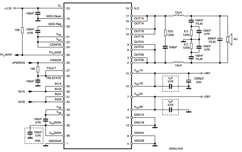
350 watt mono amplifier Stereo circuit in datasheet here