Posts

Showing posts with the label Filter

Filter PreAmp Subwoofer

Image
Acoustic spectrum is extended by the 20Hz frequency is very low and reaches as high frequency 20000Hz. In the low frequency is lowered sense of direction. This reasoning leads us to attribute to the speaker's use of very low frequency. Making it to you we propose to distinguish these frequencies, in order for him to lead us on a suitable amplifier. Acoustic filter are met at different points in the sound system. Applications knownest they are filter baxandal to organize low-and high-frequency tones and crossover filter where the acoustics are separated in the subareas, for it leads to the appropriate speakers. Applications that you can we propose is a simple filter that limits the acoustic region (20-20000Hz) in 20-100Hz region. With manufacturing, we propose that you can you can make an active filter for you lead a very low frequency loudspeaker. With this you will put a big one between speaker HIFI speakers from you. In order for you to have a complete picture of sound you will n...
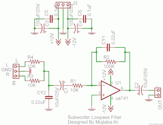
Subwoofer Lowpass Filter using uA741 Single Op Amp Ic Project

Image
This is the simplest Sub woofer Low Pass filter Circuit using uA741 single op amp ic . The circuit is very low cost with respect to their work. The cut off frequency of this circuit is 25Hz to 80Hz maximum. Using this circuit , you can easily design a 2.1 Sub-woofer Speaker System at your own Home. The circuit contains very few components.In Pakistan, the cost of this circuit with PCB is Rs:45 The same circuit is working in my own hand made sub-woofer system. Parts List:   R1,R3,R4 = 10K 1/4W R2=100K 1/4W CY1,CY2 = 0.22uF Polyester C1,C2 = 10uF/25V Electrolytic IC1 = uA741A Single Op-Amp Ic + 8 Pin Ic Socket 3 Pin Male & Female Connector x 2 2 Pin Male & Female Connector x 1 PCB as in required size 4.5 cm x 3.4 cm

Audio Filter Circuits

Image
The circuit as shown gives the bandpass operation the transfer function calculated from FBP(s) = where = 1 + s/Qo>0 + s2/w02. The cut-off frequency, 0, and the Q-factor are given by 0 = g/C and Q = gR/2 where g is the transconductance at room temperature. Interchanging the capacitor C with the resistor R at the input of the circuit high-pass operation is obtained. A low-pass filter is obtained by applying two parallel connections ctf R and C as shown in Fig. 2. The low-pass operation may be much improved with the circuit as given in Fig. 3. Audio Filter Circuits Here the gain and Q may be set up separately with respect to the cut-off frequency according to the equations Q = 1/fB = 1 + R2/R!, A = Q2 and 0 = g ffi/C.

Project of Voice Bandwidth Filter Circuit Diagram

Image
This circuit passes frequencies in the 300Hz - 3.1kHz range, as present in human speech. The circuit consists of cascaded high-pass and low-pass filters, which together form a complete band-pass filter. One half of a TL072 dual op amp (IC1a) together with two capacitors and two resistors make up a second-order Sallen-Key high-pass filter. With the values shown, the cut-off frequency (3dB point) is around 300Hz. As the op amp is powered from a single supply rail, two 10kO resistors and a 10µF decoupling capacitor are used to bias the input (pin 5) to one-half supply rail voltage. Voice Bandwidth Filter Circuit Diagram   Voice Bandwidth Filter Circuit Diagram The output of IC1a is fed into the second half of the op amp (IC1b), also configured as a Sallen-Key filter. However, this time a low-pass function is performed, with a cut-off frequency of about 3.1kHz. The filter component values were chosen for Butterworth response characteristics, providing maximum pass-band flatness. Overal...

3khz Low Pass Filter and Audio Amplifier Circuit Diagram

Image
This circuit uses a switched capacitor filter IC from National Semiconductor to filter signals with frequencies higher than the 3KHz needed for voice audio. The schematic includes an audio amplifier that is designed to drive a standard audio head phone.  The circuit is described in more detail in the receiver section of Dave Johnson's Handbook of Optical Through the Air Communications.(this link is off-site)  3khz Low Pass Filter and Audio Amplifier Circuit Diagram  

DOD Wah Filter DOD 545

Image

HQ Notch Filter Without Close Tolerance Components Project

Image
This is a electronic HQ Notch Filter Without Close-Tolerance Components Project . A notch for a narrow frequency band of a few per cent or even less normally requires close-tolerance components. At least, that’s what we thought until we came across a special opamp IC from Maxim. In filters with steep slopes, the component tolerances will interact in the complex frequency response. This effect rules out the use of standard tolerance components if any useful result is to be achieved. The circuit shown here relocates the issue of the value-sensitive resistors that determine the filter response from ‘visible’ resistors to ready available integrated circuits which also make the PCB layout for the filter much simpler. The operational amplifiers we’ve in mind contain laser-trimmed resistors that maintain their nominal value within 1‰ or less. For the same accuracy, the effort that goes into matching individual precision resistors would be far more costly and time consuming. The desired notch (...

Simple Subwoofer Lowpass Filter using uA741 Single Op Amp Ic

Image
This is the simplest Sub woofer Low Pass filter Circuit using uA741 single op amp ic.The circuit is very low cost with respect to their work. The cut off frequency of this circuit is 25Hz to 80Hz maximum. Using this circuit , you can easily design a 2.1 Sub-woofer Speaker System at your own Home. The circuit contains very few components.In Pakistan, the cost of this circuit with PCB is Rs:45. The same circuit is working in my own hand made sub-woofer system.So Try this  Sub-woofer Low-pass Filter using uA741 Single Op-Amp Ic  Circuit Diagram Parts List: R1,R3,R4 = 10K 1/4W R2=100K 1/4W CY1,CY2 = 0.22uF Polyester C1,C2 = 10uF/25V Electrolytic IC1 = uA741A Single Op-Amp Ic + 8 Pin Ic Socket 3 Pin Male & Female Connector x 2 2 Pin Male & Female Connector x 1 PCB as in required size 4.5 cm x 3.4 cm

Filter FSK Circuit Diagram

Image
FSK Frequency-Shift Keying is a form of frequency modulation in which the modulating signal changes the output frequency. between predetermined values​​. If problems arise in FSK demodulation signal is shown using this filter. The Frequency-Shift Keying filter is very simple and can be built into a phone plug.   Filter FSK Circuit Diagram   The diagram shows a low-pass filter made ​​of R1 and C2. This filter has a cutoff frequency. about 1.6 KHz. Once the "0" and "1" signals from FSK tones are sent as 1.2 kHz and 2.4 kHz respectively filter removes all the undesired signals. Both D1 and D2 ensure that the FSK signal is limited to about + / - 600 mV amplitude. It can be connected to a speaker or headphone output. components C1 = 0.0082 C2 = 0.018 R1 = 5.6kΩ D1 = D2 = 1N4148