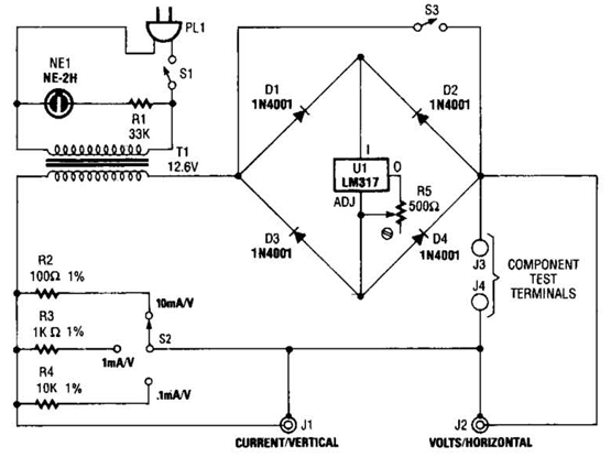
Low voltage Power Supply Circuit Diagram
If you want to check the behaviour of an electronic circuit at low voltages, an adjustable power supply as shown here may be helpful. Powered from a 3 to 16 volts source (DC for sure), it will provide a stable output voltage in the 0 to 1.5 V range.
Adjustable Low-voltage Power Supply Circuit Diagram
Adjustable Low-voltage Power Supply Circuit Diagram

Multiturn trimpot P1 allows the output volt-age to be adjusted with good precision. The BC337-400 output transistor raises the out-put current to about 200 mA bearing in mind that the minimum supply voltage is 3.5 V. The transistor’s dissipation should be taken into account, and a more power ful t ype used if necessary.
T1 may be omitted and R2 replaced with a wire link if you are happy with 3 mA at 3 volts out, 10 mA at 6 V or 20-30 mA at 10-16 V.
These values represent the maximum output current of the TLC271 op amp. Without T1, the minimum supply voltage is 3.0 V.
Author:Vladimir Mitrovic - Copyright: Elektor


Comments
Post a Comment