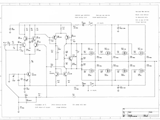
This 5.1 surround amplifier circuit schematic use the IC AN7168 as the main component from this circuit . Minimum voltage required 12V and maximum voltage 24V , I recomended it 12 V because the voltage support on are components. But if you want to better a loud sound you can raise it. Maximum power output 40W with impedance 4 ohm . This 5.1 surround amplifier circuit schematic also support to make surround sound or 5.1 speaker. Use this amplifier on rear speaker , left right , and center but dont use to subwoofer speaker. See 5.1 surround amplifier circuit schematic below : Click to view large If you want to make a 5.1 surround sound you must make 5 the circuit of 5.1 surround amplifier circuit schematic , for left and right speaker , rear left and right speaker , and center speaker. Use the subwoofer speaker with support amlplifier subwoofer circuit .
Before we start today's blog post, I think I really need to clarify what we’re discussing. I’ve recently got back into vinyl in a big way. Part of the reason for this is the fantastic “Vinyl Decision” in Taipei, run by a couple of very fine gentlemen by the names of Mark and Terry ( https://www.facebook.com/VinylDecision / http://www.vinyldecision.com/ ). If you're in Taipei, and like music, pay them a visit. A recent purchase from there brought back memories of trying again, and again (and again) to play guitar like my guitar heroes as a teenager in the 1980s. In fact, vinyl is making quite a comeback worldwide. A lot of people are realizing that digital versions just lack some of the personality that vinyl can provide. Many of them are buying old record players/turntables and wiring them up to their modern amps. However, they are often disappointed to find that the output audio is very quiet and lacking bass. This is because records are/were recorded using a very specific f...
Description Circuit showing a Burglar Alarm.Here we have used a ldr and a switching transistor for making this circuit .When the light coming towards the ldr during the period the ldr have low resistance so the buzzer will on.When the light going away the ldr during the period the ldr have high resistance so the transistor will off.Here you need a 12 volt power supply Burglar Alarm Using LDR and BC 548 Circuit diagram Components Required Resistor 10 k(preset) Transistor BC 548 LDR Buzzer


Comments
Post a Comment