Posts

Showing posts from June, 2017

How to Build Unregulated Linear Power Supply
Image
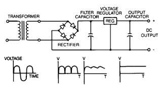
Unregulated power supplies contain four basic components: transformer, rectifier, filter capacitor, and a bleeder resistor. This type of power supply, because of Us simpticity, is the least costly and most reliable for low power requirements. The disadvantage is that the output voltage is not constant It will vary with the input voltage and the load current, and the ripple is not suitable for electronic applications. The ripple can be reduced by changing the filter capacitor to an LC (inductor-capacitor) filter but the cost to make this change would make use of the regulated linear power supply a more economical choice.

Wireless Speakers Offer Excellent Sound Selection

Image
Technology is constantly evolving and introducing new products to an already full line of home theater products. While not the newest kids on the block, wireless speaker technology is also advancing at a rate that prices are no longer out of reach of the average consumer and the value of being able to move your speakers around without going to the work of rewiring is appealing to consumers on an increasingly large scale.  Wireless Speakers I always try to keep in mind when buying new electronics and electronic components that this year’s technology will sell at half the price this time next year. For this reason I have a hard time investing in the latest and greatest when it comes to technology and tend to remain exactly one generation behind the curve when buying new products. I like to save money whenever possible and in most cases my like of saving money outweighs my like of having new gadgets and gizmos at the high price they often command. I also have a nasty habit of keepi...

Spining BLDC motors at super Slow speeds with Arduino and L6234

Image
I used specialized triple half bridge IC L6234 (~ 8$). You can make the same spending less money (but more time) with MOSFET transistors or other IC. L6234 datasheet is surprisingly useless. Go straight to Application Note AN1088 instead. I added current limiting resistors (1kΩ) to all INputs and ENable pins, a bunch of capacitors recommended in application note and current sensing shunt resistor 0.6Ω (big blue one). [ ]

Capacitive Sensor Circuit Schematic Diagram

Image
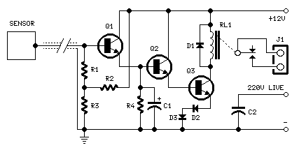
Special design for shop-windows animation Useful for many types of touch controls Circuit diagram: Parts: R1,R2_____1M 1/4W Resistors R3,R4____47K 1/4W Resistors C1_______10µF 25V Electrolytic Capacitor C2______470pF 630V Ceramic or Polyester Capacitor D1-D3____1N4002 100V 1A Diodes Q1-Q3_____BC337 45V 800mA NPN Transistors RL1_______Relay with SPDT 2A @ 220V switch Coil Voltage 12V. Coil resistance 200-300 Ohm J1________Two ways output socket Sensor____Aluminium or copper thin sheet with the dimensions of a post-card, glued at the rear of the same (about 15x10.5 cm.) Thin screened cable Circuit Description:  The purpose of this circuit is to animate shop-windows by means of a capacitive sensor placed behind a post-card-like banner. The card is placed against the glass inside the shop-window, and the visitor can activate the relay placing his hand on the card, from the outside. Especially suited for toy-shops, the circuit can activate model trains, small electric racing cars, lig...

Simple DCF77 Preamplifier Circuit Diagram

Image
Simple DCF77 Preamplifier Circuit Diagram . A popular project among microcontroller aficionados is to build a radio-controlled clock. Tiny receiver boards are available, with a pre-adjusted ferrite antenna, that receive and demodulate the DCF77 time signal broadcast from Mainf lingen in Germany. DCF77 has a range of about 1,000 miles. All the microcontroller need do is decode the signal and output the results on a display. The reception quality achieved by these ready-made boards tends to be proportional to their price. In areas of marginal reception a higher quality receiver is needed, and a small selective preamplifier stage will usually improve the situation further. The original ferrite antenna is desoldered from the receiver module and connected to the input of the preamplifier. This input consists of a source follower (T1) which has very little damping effect on the resonant circuit. A bipolar transistor (T2) provides a gain of around 5 dB. The output signal is coupled to the ant...

DIY soldering robot

Image
The DIY soldering robot which we have been building in our spare time over the past few months is now working and we have been able to solder some test Raspberry Pi expansion board headers with the machine. [ ]

300W Subwoofer Power Amplifier Wiring Circuit Diagram

Image
Circuit Diagram Description Please agenda that the blueprint for this amp has been upgraded, and it is now recommended for connected aerial ability into 4 Ohms, but You will charge to go to extremes with the heatsink ( fan cooling is awful recommended). It was originally advised for “light” alternate duty, acceptable for an equalised subwoofer arrangement (for archetype application the ELF assumption – see the Project Page for the advice on this circuit). Where connected aerial ability is required, addition 4 achievement transistors are recommended, active in the aforementioned way as Q9, Q10, Q11 and Q12, and application 0.33 ohm emitter resistors. Continuous ability into 8 ohms is about over 150W (250W for ±70V supplies), and it can be acclimated after added transistors at abounding ability into an 8 ohm amount all day, every day. The added transistors are alone bare if you appetite to do the aforementioned affair into 4 ohms at best accumulation voltage! Do not alike anticipate...

TDA2030 complete tone control

Image
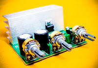
At this time I present a series of amplifiers that use IC TDA2030, but this series is equipped with a tone control. Tone controls include Bass, Treebel, and Volume. Power amplifier and tone control has been put together in a single PCB. As well as its power supply circuit was also used as one with the power amp, and tone control. Making it easier in the installation and will look neat. Schematics Layout PCB PCB design This amplifier is a mono amplifier type, can be modif for guitar amplifiers. If not coupled amplifier (mic preamp) then you must deactivated potensio treble and bass, why? because if not using a mic preamp and still maintain potensio treble and bass sound input (input) from the guitar will not or the maximum discharge is not tight on the speakers. So you must deactivated a way to decide which directly connected capacitor with the tone control circuit, and capacitor were connected directly to potensio volume and input jack.

Great Brands for Good Prices on Auto Sound Systems

If you are one of the many people across the country considering a new auto sound system, there is a great deal of good news. First of all, it is very possible to find a good bargain on a nice sound system for your car, truck, or SUV if you are willing to shop online and install the system yourself. The problem often lies not in the cost of the system but the price of the installation. However, the cost of installation is well worth the dollar amount for many of us who really have no clue what to do as far as a project of that scope goes. I for one am among the electronically challenged and not really willing to risk my dash board for an experiment in frustration and failed electronics. That being said, there are many who are either perfectly and wonderfully capable of installing a nice auto sound system or are fortunate enough to know someone or someone who knows someone who is. Gaining Up, finding a great bargain online is probably the best way to go-provided you've actually been...

Smart Voltage Stabilizer Using PIC16F877A

Image
Voltage stabilizers are used for  many appliances in homes,  offices and industries. The  mains supply suffers from large voltage  drops due to losses on the distribution  lines en route. A voltage stabilizer  maintains the voltage to the appliance  at the nominal value of around 220  volts even if the input mains fluctuates  over a wide range. Here is the circuit of an automatic  voltage stabilizer that can be adapted  to any power rating. Its intelligence  lies in the program on PIC16F877A—a  low-cost microcontroller that is readily  available. The circuit, when used with  any appliance, will maintain the voltage  at around 220V even if the input  mains voltage varies between 180V  and 250V. Here the circuit is shown for a  5A stabilizer. It acts within 100ms to  produce a smoothly varying output  whenever input mains voltage changes.  (Servo stabilizers move a variable...

Combine stereo input to one output

Image
Here , I will give a circuit of schemes that are used to combine 2 pieces input or stereo to 1 input mono. Why 2 inputs in to one because, if we need a stereo amplifier we want to become a stronger by combining the two input into one input, so that a higher power output. Actually without any circuit above we can combine stereo amplifier into mono, but the sound output less than the maximum , need for this additional combiner circuit. Part List = R1______150K R2______920R R3______150K R4______920R R5______920R U1______NE5532 For balance _: R1 / R2=R3 / R4 For balance _: R1 = R3 Gain ______: R5 / R1 = R5 / R3