Case study implementation and example of CAN BUS
Aim:
1. What is CAN?
CAN,which stands for Controller Area Network, is the serial communication protocol internationally standardized by ISO *1. The automobile industry has hitherto witnessed the advent of various electronic control systems that have been developed in pursuit of safety, comfort, pollution prevention, and low cost. These control systems, however, presented a drawback in that since the communication data types, required reliability, etc. Differed between each system, they were configured in multiple bus lines, resulting in increased wire harnesses. Therefore, the need arose for reducing the number of wire harnesses, transferring large amounts of data at high speed via multiple LANs, and so on. To meet the need, BOSCH, an electrical equipment manufacturer in Germany, developed CAN in 1986 as a communication protocol for automotives. Thereafter, CAN was standardized in ISO 11898 and ISO 11519, establishing itself as the standard protocol for in-vehicle networking in Europe now.
Today, CAN is widely accepted for its high performance and reliability, and is used in a broad range of fields from FA devices and ships to medical and industrial equipment. Figure 1 schematically shows how in-vehicle networking will be conceived. In this conception, CAN and the other communication protocols developed concurrently made it possible for multiple LANs to exchange data efficiently via a gateway.

2. Why CAN?
- Mature Standard
ü CAN protocol more than 16 years
ü Numerous CAN products and tools on the market
- Hardware implementation of the protocol
ü Combination of error handling and fault confinement with high transmission speed (up to 1Mb/s)
- Simple Transmission Medium
ü Twisted pair of wires is the standard, but also just one wire will work
ü Other links works, too: Opto - or radio links
- Excellent Error Handling
ü CRC error detection mechanism
- Fault Confinement
ü Built-in feature to prevent faulty node to block system
- Most used protocol in industrial and automotive world
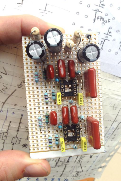
Example of CAN bus

Example application of CAN bus
2. Basic Concept of the CAN Protocol
The CAN protocol includes the transport, data link, and physical layers of the basic OSI*1 reference model. Figure 5 shows the defined items of each layer of the basic OSI reference model in the CAN protocol. The data link layer is divided into MAC*2 and LLC*3 sub-layers, of which the MAC sub-layer constitutes the nucleus of the CAN protocol. The function of the data link layer is to put the signals received from the physical layer together into a meaningful message to provide a procedure for data transmission control such as transmission error control. More specifically, this includes assembling messages into a frame, arbitrating data collision, returning ACK, and detecting or notifying errors. These functions of the data link layer normally are executed in hardware by the CAN controller. For the physical layer, the protocol defines the manner in which signals are actually transmitted and the bit timing, bit encoding, and synchronization procedures. However, this does not mean that the signal levels, communication speeds, sampling point values, driver and bus electrical characteristics, and connector forms are defined specifically by the CAN protocol. All of these must be selected for each system by the user.
In CAN specifications of BOSCH, there are no definitions with respect to the electrical characteristics, etc. Of transceivers and buses. In the ISO standards for the CAN protocol, i.e., ISO11898 and ISO11519-2, however, the electrical characteristics, etc. of transceivers and buses are defined in each.
*1 : OSI stands for Open System Interconnection.
*2 : MAC stands for Medium Access Control
*3 : LLC stands for Logical Link Control

Figure2. Basic OSI Reference Model of ISO and the CAN Protocol
3 CAN Protocol
Types of Frames
Communication is performed using the following five types of frames.
• Data frame
• Remote frame
• Error frame
• Overload frame
• Inter frame space
Of these frames, the data and the remote frames need to be set by the user. The other frames are set by the hardware part of CAN.
The data and the remote frames come in two frame formats: standard and extended. The standard format has a 11-bit ID, and the extended format has a 29-bit ID.
Data Frame
The data frame is used by the transmit unit to send a message to the receive unit, and is the most fundamental frame handled by the user.
The data frame consists of seven fields.
Figure 2 shows the structure of the data frame.
(1) Start of frame (SOF)
This field indicates the beginning of a data frame.
(2) Arbitration field
This field indicates the priority of a frame.
(3) Control field
This field indicates reserved bits and the number of data bytes.
(4) Data field
This is the content of data. Data in the range 0 to 8 bytes can be transmitted.
(5) CRC field
This field is used to check the frame for a transmission error.
(6) ACK field
This field indicates a signal for confirmation that the frame has been received normally.
(7) End of frame
This field indicates the end of a data frame.
Remote frame

Difference between dada frame and remote frame
ž The remote frame does not have a data field, and that the RTR bit in its arbitration field is of a recessive level.
ž The data frame without a data field and the remote frame can be discriminated by the RTR bit.
ž What does the data length code of the remote frame that has no data fields indicate?
• It indicates the data length code of the corresponding data frame.
ž For what is the data frame without a data field used?
ž For example, this data frame may be used by each unit to confirm or respond for connection periodically, or to place real information in the arbitration field itself.
Error frame
This frame is used to notify an error that has occurred during transmission. The error frame consists of an
error flag and an error delimiter. Error frames are transmitted by the hardware part of CAN.
Figure 24 shows the structure of the error frame.
(1) Error flag
There are two types of error flags: active-error flag and passive-error flag.
• Active-error flag: 6 dominant bits
• Passive-error flag: 6 recessive bits
(2) Error delimiter
The error delimiter consists of 8 recessive bits
Overload frame
The overload frame is used by the receive unit to notify that it has not been prepared to receive frames yet.
It consists of an overload flag and an overload delimiter.
(1) Overload flag - 6 dominant bits.
(2)Overload delimiter - 8 recessive bits.
Error flag overlapping
Depending on timing as for the error flag, overload flags may overlap one on top of another, up to 12 bits in total length.
Interframe space

• Used to separate the data and the remote frames
• Are separated from the preceding frame by an inserted
Interframe space
CAN message format
- SOF: Start Of Frame
- CRC: Cyclic Redundancy Code
- ACK: Acknowledge
- EOF: End of Frame
- IFS: Inter Frame Space
CAN controller modes
ž Error active
• Normal operating mode for a controller
• Messages can be received and transmitted
• On detecting an error an active error flag is sent
ž Error passive
• A mode entered when the controller has frequent problems in transmitting or receiving messages
• Messages can be received and transmitted
• On detecting an error while receiving, a passive error flag is sent
ž Bus off
• Entered if the controller has serious problems with transmitting messages.
• No messages can be transmitted or received until the CAN controller is reset by host micro controller or processor.
Higher layer protocol
ž The CAN protocol defines only the ‘physical’ and low ‘data’ link layers.
ž The HLP defines:
• Start-up behavior
• Definition of message identifiers for the different nodes
• Flow control
– Transportation of messages greater than 8-bytes
• Definition of contents of data frames
• Status reporting in the system
ž Some HLP: CANopen , DeviceNet, SAE J1939 (Heavy vehicles)
CAN application
ž Building Automations
• Heating control, Air conditioning(AC), Security(fire, burglar…), Access control, Light control
ž Domestic & Food distribution appliances
• Washing machines, Dishes cleaner, self service bottle distributors connected to internet.
ž Automotive & Transportation
• Dash board electronics, Comfort electronics
ž Production Automation
• Control and link of production machines, production control, Tool machines.
ž Medical
ž Agriculture Harvester Machines
• Seeding/Sowing machines, Tractor control, Control of live stock breeding equipment.
Conclusion
CAN is ideally suited in applications requiring a large number of short messages with high reliability inrugged operating environments. Because CAN is message based and not address based, it is especially well suited when data is needed by more than one location and system-wide data consistency is mandatory. Fault confinement is also a major benefit of CAN. Faulty nodes are automatically dropped from the bus, which prevents any single node from bringing a network down, and ensures that bandwidth is always available for critical message transmission. This error containment also allows nodes to be added to a bus while the system is in operation, otherwise known as hot-plugging. The many features of the TI CAN transceivers make them ideally suited for the many rugged applications to which the CAN protocol is being adapted. Among the applications finding solutions with CAN are automobiles, trucks, motorcycles, snowmobiles trains, buses, airplanes, agriculture, construction, mining.

Comments
Post a Comment