Posts

Showing posts from February, 2017

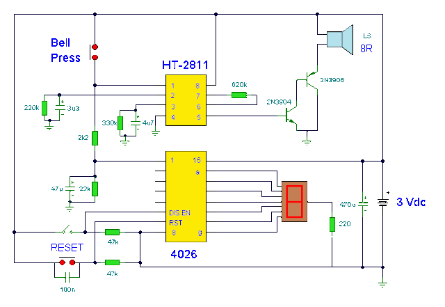
Doorbell with Counter Circuit Diagram
Image
This circuit is a doorbell with counter , that means it counts how many times the bell is triggered . It uses a chip synthesizer sound, the HT -2811 ms nothing prevents you from using another device sound generator . The HT -2811 reproduces the sound of a " ding-dong" doorbell . Besides this ic , the circuit includes a CMOS 4026 and Display Driver IC which counts the total number of visitors .  Electronic Doorbell with Counter Circuit Diagram

Simple Mobile Voltage Regulator Circuit Diagram

Image
Build a Simple Mobile Voltage Regulator Circuit Diagram. This simple mobile voltage regulator circuit diagram may save your two meter or CB transceiver if the voltage regulator fails. The 2N3055 should be heat sinked if current drawn by the rig is in excess of 2 A on transmit. This simple mobile voltage regulator circuit diagram will do little under normal operating conditions, but could save expensive equipment if the vehicle`s electrical system loses regulation. Simple mobile voltage regulator circuit diagram

Subwoofer Lowpass Filter using uA741 Single Op Amp Ic Project

Image
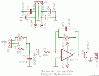
This is the simplest Sub woofer Low Pass filter Circuit using uA741 single op amp ic . The circuit is very low cost with respect to their work. The cut off frequency of this circuit is 25Hz to 80Hz maximum. Using this circuit , you can easily design a 2.1 Sub-woofer Speaker System at your own Home. The circuit contains very few components.In Pakistan, the cost of this circuit with PCB is Rs:45 The same circuit is working in my own hand made sub-woofer system. Parts List:   R1,R3,R4 = 10K 1/4W R2=100K 1/4W CY1,CY2 = 0.22uF Polyester C1,C2 = 10uF/25V Electrolytic IC1 = uA741A Single Op-Amp Ic + 8 Pin Ic Socket 3 Pin Male & Female Connector x 2 2 Pin Male & Female Connector x 1 PCB as in required size 4.5 cm x 3.4 cm

DC motor driver with H Bridge IC L293D

Image
Making a DC motor driver with H-Bridge technique can use IC L293D as in the article "DC Motor Driver H-Bridge L293 (2 Motor DC)"is. DC motor driver L293D can be used to control the DC motor 2 pieces at once. DC Motor Driver L293D can be used to control a DC motor continuously or with a PWM technique. Dc motor driver circuit in the article "DC Motor Driver H-Bridge L293 (2 Motor DC)" only use IC L293D only. For more details see the following figure. Working system of DC motor driver L293D is to provide control signals in the form of logic or pulse to the input lines 1A - 1B for DC motor control M1 and the input 2A - 2B for the control of DC motor M2 with the following conditions: Input A Input B Motor DC 0 0 Motor silent 1 0 motor rotates counterclockwise 0 1 Motor berputer clockwise 1 1 Motor silent Description: Enable Input given a logic 1 to obtain such data in the table above.

Simple VHF FM Aircraft Receiver

Image
VHF FM Aircraft Receiver is a supererogation receiver developed for listening to FM transmitters but also tunes the aircraft band and the top portion of the FM broadcast band. Receives both AM and FM (107mHz to 135 MHz). You can use this receiver with the any FM transmitter. The receiver is amazingly simple using only one transistor for the receiver section and one IC for the audio section. This circuit is a self-quenching regenerative RF receiver also known as a super regenerative receiver. A superregenerative receiver performs two basic functions.    First it feeds back a portion of the received signal from it’s output in phase to its input; and second a super audible quenching oscillator drives the amplifier through the point of oscillation and maximum sensitivity and then quenches the oscillation repeatedly. This keeps the feedback from driving the circuit into self-oscillation and allows the signal to be regenerated over and over again. In this version of the circuit, ...

Make a Warning Light and Marker Light Circuit Diagram

Image
Make a Warning-light-and-marker-light. This is a led flasher light, A flashing light of high brightness and short duty cycle is often desired to provide maximum visibility and battery life. This necessitates using an output transistor, which can supply the cold filament surge current of the lamp while maintaining a low saturation voltage. The oscillation period and flash duration are determined in the feedback loop, while the use of a photo transistor sensor minimizes sensitivity variations. Warning Light and Marker Light Circuit Diagram

7 segment display Arduino

Image
The aim of this article demonstrate how the Arduino can run on 7-segment display.   We used a SA56-11GWA which is a single display with common anode, it means that the anode is common to all digits, and to the point. A display consists of 8 LEDs, 7 form the figure and 1 point decimal.A conversion between decimal and what we intend to show the binary information that you receive is called the BCD (Binary Coded Decimal). In terms of hardware, each LED work individually, so each of the segments has to lead a limiting resistor, in this case, each digit has an operating voltage of 2.2V and consumes 20mA.   If the voltage is 5volts, we need the resistor fall 5-2.2 = 3.8V, by Ohm's Law we can calculate, R = V  res  / I  led  R = 3.8 / 0.020 = 190 Ω +/- 20% (let's use a resistor with 220Ω).   This applies to this display SA56-11GWA used as an example, other values ​​may be different, it is useful to calculate the required resistance value. Decimal The A  ...

Project of Overtone Crystal Oscillator Circuit Diagram

Image
Build a simple Project of Overtone Crystal Oscillator Circuit Diagram. A crystal oscillator is an electronic oscillator circuit that uses the mechanical resonance of a vibrating crystal of piezoelectric material to create an electrical signal with a very precise frequency.   Overtone Crystal Oscillator Circuit Diagram This frequency is commonly used to keep track of time (as in quartz wristwatches), to provide a stable clock signal for digital integrated circuits, and to stabilize frequencies for radio transmitters and receivers. The most common type of piezoelectric resonator used is the quartz crystal, so oscillator circuits incorporating them became known as crystal oscillator s, but other piezoelectric materials including polycrystalline ceramics are used in similar circuits..  This oscillator is designed for overtone crystals in the 20-100 MHz range operating in the third and fifth mode. Operating frequency is determined by the tuned circuit.

Simple Automatic Load Sensing Power Switch

Image
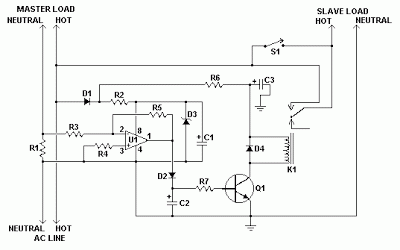
This circuit will automatically switch on several mains-powered "slave" loads when a "master" load is turned on. For example, it will switch on the amplifier and CD player in a stereo system when the receiver is turned on. It works by sensing the current draw of the "master" device through a low value high wattage resistor using a comparator. The output of that comparator then switches on the "slave" relay. The circuit can be built into a power bar, extension cord or power center to provide a convenient set of "smart" outlets that switch on when the master appliance is powered (turn on the computer monitor and the computer, printer and other peripherals come on as well). .  Simple Automatic Load Sensing Power Switch Circuit Diagram Parts Part               Total Qty. Description C1, C3               2            ...

Burglar Alarm Using LDR and BC 548 Circuit diagram

Image
Description  Circuit showing a Burglar Alarm.Here we have used a ldr and a switching transistor for making this circuit .When the light coming towards the ldr during the period the ldr have low resistance so the buzzer will on.When the light going away the ldr during the period the ldr have high resistance so the transistor will off.Here you need a 12 volt power supply Burglar Alarm Using LDR and BC 548 Circuit diagram    Components Required       Resistor                    10 k(preset)       Transistor                    BC 548        LDR         Buzzer

Simple PIC Controlled Relay Driver Circuit Diagram

Image
This is a simple project of PIC Controlled Relay Driver circuit is a relay driver that is based on a PIC16F84A microcontroller. The board includes four relays so this lets us to control four distinct electrical devices. The controlled device may be a heater, a lamp, a computer or a motor. To use this board in the industrial area, the supply part is designed more attentively. To minimize the effects of the ac line noises, a 1:1 line filter transformer is used. The transformer is a 220V to 12V, 50Hz and 3.6VA PCB type transformer. The model seen in the photo is HRDiemen E3814056. Since it is encapsulated, the transformer is isolated from the external effects. A 250V 400mA glass fuse is used to protect the circuit from damage due to excessive current. A high power device which is connected to the same line may form unwanted high amplitude signals while turning on and off. To bypass this signal effects, a variable resistor (varistor) which has a 20mm diameter is paralelly connected to the...

Crystal Controlled Reflection Oscillator Circuit Diagram

Image
How to build a Crystal-controlled-reflection-oscillator circuit diagram . This is a simple crystal controlled reflection oscillator circuit, this unit is easily tunable and stable, consumes little power, and costs less than other types of oscillators tlmt operate at the same frequencies. This unusual combination of features is made possible by a design concept that includes operation of the transistor well beyond the 3 dB frequency of its current-versus- frequency curve.   Crystal Controlled Reflection Oscillator Circuit Diagram The concept takes advantage of newly available crystals that resonate at frequencies up to about 1 GHz.The emitter of transistor Q is connected with variable capacitor Cl and series-resonant crystal X. The emitter is also connected to ground through bias resistor Rl. The base is connected to the parallel combination of inductor L and capacitor C3 through DE-blocking capacitor and C4 and is forward biased with respect to the emitter by resistors R3 and...

New Liquipel – Make Your Phone Watersafe

Image
Liquipel™ is a revolutionary process that applies a watersafe™ coating to your electronic devices to protect them in the event of accidental exposure to liquids. It is not visible to the human eye, virtually undetectable and Liquipel™ will not compromise the look, feel, and performance of your electronics. Liquipel™ is a Nano-Coating that is applied though a propriety process. This process starts by placing devices into the chamber of the Liquipel™ Machine. The Machine then removes all the air to create a vacuum, a special formula is then introduced as a vapor. The vapor then permeates the entire device inside and out, Liquipel™ then bonds to the device on a molecular level, leaving your device watersafe™ for years to come. Check out our GITEX 2012 Trade video coverage to see Liquipel in action.

Basic PLC Ladder Programming Examples 19

Image
Basic PLC Ladder Programming Examples 19 Basic PLC Ladder Programming Training Examples for Beginners.  Hi friends, here we are starting unique a series of Free Training on PLC Ladder Programming & tutorials. These PLC Ladder Programs are important to learn basics of Ladder programs.   PLC Ladder Practice Problem:  Entry/Exit Control of the Underground Car Park. ·        The entry/exit of the underground car park is a single lane passage which needs the traffic lights to control the cars. Red lights prohibit cars entering or leaving while green lights allow cars to enter or leave. ·        When a car enters the passage from the entry of the ground floor, the red lights both on the ground floor and the basement will be ON, and the green lights will be OFF. Any car entering or leaving is prohibited during the process till the car passes through the passage completely. When the passage is clear...

230 400 Watt Power Amplifier MOSFET

Image
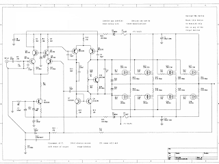
Amplifier circuit below is a series of amplifiers with the amplifier transistor and mosfet. This amplifier output power ranging from 230W up to 400W. 230 - 400 Watt Power Amplifier

DIAGRAMMING SENTENCES

Image
Another Example: Click on the diagram to ... Try these sentences: Diagram from Florey Compound subject and compound ... Click on the diagram to ... The diagram of a simple ... ... For Diagramming A Sentence ... help diagramming sentences ...

Chip Theremin Circuit Diagram

Image
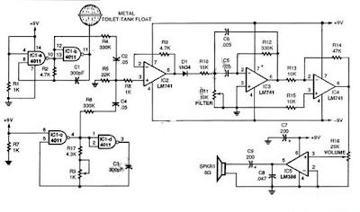
This schematic diagram show a single chip Theremin circuit.  Theremin is an electronic music instrument which sense hand movement to control the tones/frequency.  This Theremin circuit uses two separate Colpitts LC oscillators to produce a beat frequency.  The frequencies of  two Colpitts LC oscillators are mixed and then rectified. This rectification  demodulate the mixed signal to get the beat frequency which is in audible range. This beat frequency or difference is the real  Theremin’s output. The oscillator is operated at high frequency (inaudible) to get wide audible frequency range of beat frequency when two oscillator output is mixed.  This circuit uses a 4011 quad gate to construct the high frequency oscillator operating at 250kHz. Here is the schematic diagram of the circuit. Single Chip Theremin Circuit Diagram The metal probe that is used to sense your  hand produces only small frequency shift in term of percentage of original frequency...

1 5V to 3V Voltage Converter

Image
A simple scheme to generate the inverter voltage from 1.5V to 3V can be made ​​on the basis of slightly modified the well-known multivibrator. Under these denominations in the scheme of the frequency converter is approximately 130 kHz. Inductance value can be calculated or chosen experimentally. But you can simply adjust the frequency of the converter to produce maximum output voltage. Schottky diode VD1 can be replaced by any other similar characteristics. 1.5V to 3V Voltage Converter Circuit Diagram   For further stabilization of the output voltage can be applied to the zener voltage of 3V – 3.3V. This scheme can be used to power a LED or low power devices based on the microcontroller, for example, MSP430. Parts list : R1,R3 : 1K R2 : 2K2 C1 : 470pF C2 : 100uF/3,3V C3 : 1000uF L1 : 470uH VD1 : 15MQ040 VT1, VT2 : BC547

Audio Filter Circuits

Image
The circuit as shown gives the bandpass operation the transfer function calculated from FBP(s) = where = 1 + s/Qo>0 + s2/w02. The cut-off frequency, 0, and the Q-factor are given by 0 = g/C and Q = gR/2 where g is the transconductance at room temperature. Interchanging the capacitor C with the resistor R at the input of the circuit high-pass operation is obtained. A low-pass filter is obtained by applying two parallel connections ctf R and C as shown in Fig. 2. The low-pass operation may be much improved with the circuit as given in Fig. 3. Audio Filter Circuits Here the gain and Q may be set up separately with respect to the cut-off frequency according to the equations Q = 1/fB = 1 + R2/R!, A = Q2 and 0 = g ffi/C.

Intregated Circuit Amplifier with Output Transformer

Image
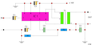
This amplifier circuit uses the output transformer as an additional amplifier in the output. You can use the transformer output transformer-old has not used but still in good condition, you can use it in this series. For this amplifier IC used is M51503L, this ic has a voltage limit of up to 7 volts only and a minimum of the incoming voltage about 2 volts. Actual output issued from the IC is 0.2 Watts, but once applied to the circuit maximum output of about 5.3 Watts. Part List : Resistor R1 = 75R R2 = 330R Capacitor C1 = 1uF C2 = 47uF C3 = 100uF C4 = 0.33uF C5 = 0.47uF Transformer T1 = Transformer Output OT240 IC IC1 = M51503L

Bass Booster with TL072

Image
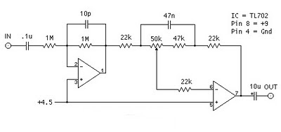
The following is megabass circuit schematic (rangkaian megabass) . The megabass circuit is a modified Baxandall tone control with no bass cut and no treble control. It boosts frequencies from about 30Hz to 160Hz can boost by 14dB. Bass Booster Schematics Note: The input capacitor can be replaced with a .01uf cap if you wish. The 10pf capacitor is optional and will start rolling off everything over 15kHz. 5pf will double this to 31kHz. The tone control requires a low impedence input. If you already have a low impedence input, the input buffer can be removed. However, the output is inverted. The opamp is not critical. A 4558 would be just fine. I do not show the parts for the +4.5 reference. Here is the +4.5 voltage divider I used. IC A4558 Pinning The A4558 is a monolithic Integrated Circuit designed for dual operational amplifier. Absolute maximum ratings of A4558 Ap-amp Supply voltage VCC 20 or ±10 V Differential input voltage VIND 20 V Input voltage VIN ±10 V Power Dissipation PD 300...

FM Booster Diagram Circuit

Image
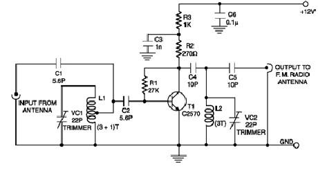
Description A low-cost circuit of an FM booster that can be used to listen programs from distant FM stations clearly. The circuit comprises a common-emitter tuned RF preamplifier wired around VHF/UHF transistor 2SC2570 ( C2570). This FM booster circuit is constructed using few common components ( not require some special components ) and provide a very good gain . To calibrate this circuit you need to adjust input/output trimmers (VC1/VC2) for maximum gain. Input coil L1 consists of four turns of 20SWG enamelled copper wire (slightly space wound) over 5mm diameter former. It is tapped at the first turn from ground lead side. Coil L2 is similar to L1, but has only three turns. Both of the trimmers are 22pF value .This FM radio signal booster needs to be powered by a 12 volts DC power supply . Circuit Diagram Source - http://www.electroniq.net/radio-frequency/fm-booster-schematic-circuit.html

metering current transformer

Image

Battery Charger using LM317 Regulator

Image
Battery Charger using LM317 Regulator This Battery Charger is very similar to the universal charger that uses the constant current load. But this is much simpler to build and can be built using only two parties, the LM317 regulator and resistance. The use of diode D is for protection against short circuits. Capacitors C1 and C2 is good voltage regulation. Resistance R2 operates a dummy load when the battery is disconnected. The idea of ​​this magazine is the output current is equal to 1.2 V, divided by the value of R1. Part List: LM317 R1 - see the values in table below R2 - 2.2 kilo-ohms 1/4W C1,C2 - 47uF/25V, or any value will do, the higher the better D - 1N4001 or any similar diode at-least 1A rated