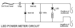
MAX231 RS 232C LED Circuit Diagram
This is the simple MAX231 RS-232C LED Circuit Diagram. Use a pair of Maxim`s 5V-powered MAX231 RS-232C transmitters as drivers to obtain a 2-color LED. The transmitters require only a singleended, 5-V input to generate ± 10 V internally.
MAX231 RS-232C LED Circuit Diagram

Their outputs are short-circuit-proof and can supply as much as 10 mA-enough to drive most LEDs. Depending on which LED you select, their currentlimiting feature might also eliminate the need for external series resistors.
Sourced By: Streampowers.blogspot.com

Comments
Post a Comment